Light amount adjusting device and optical device
a technology of light amount and adjustment device, which is applied in the direction of optics, camera diaphragms, cameras, etc., can solve problems such as unnatural image quality, and achieve the effect of satisfactory diaphragm opening shape and reduced device siz
- Summary
- Abstract
- Description
- Claims
- Application Information
AI Technical Summary
Benefits of technology
Problems solved by technology
Method used
Image
Examples
first embodiment
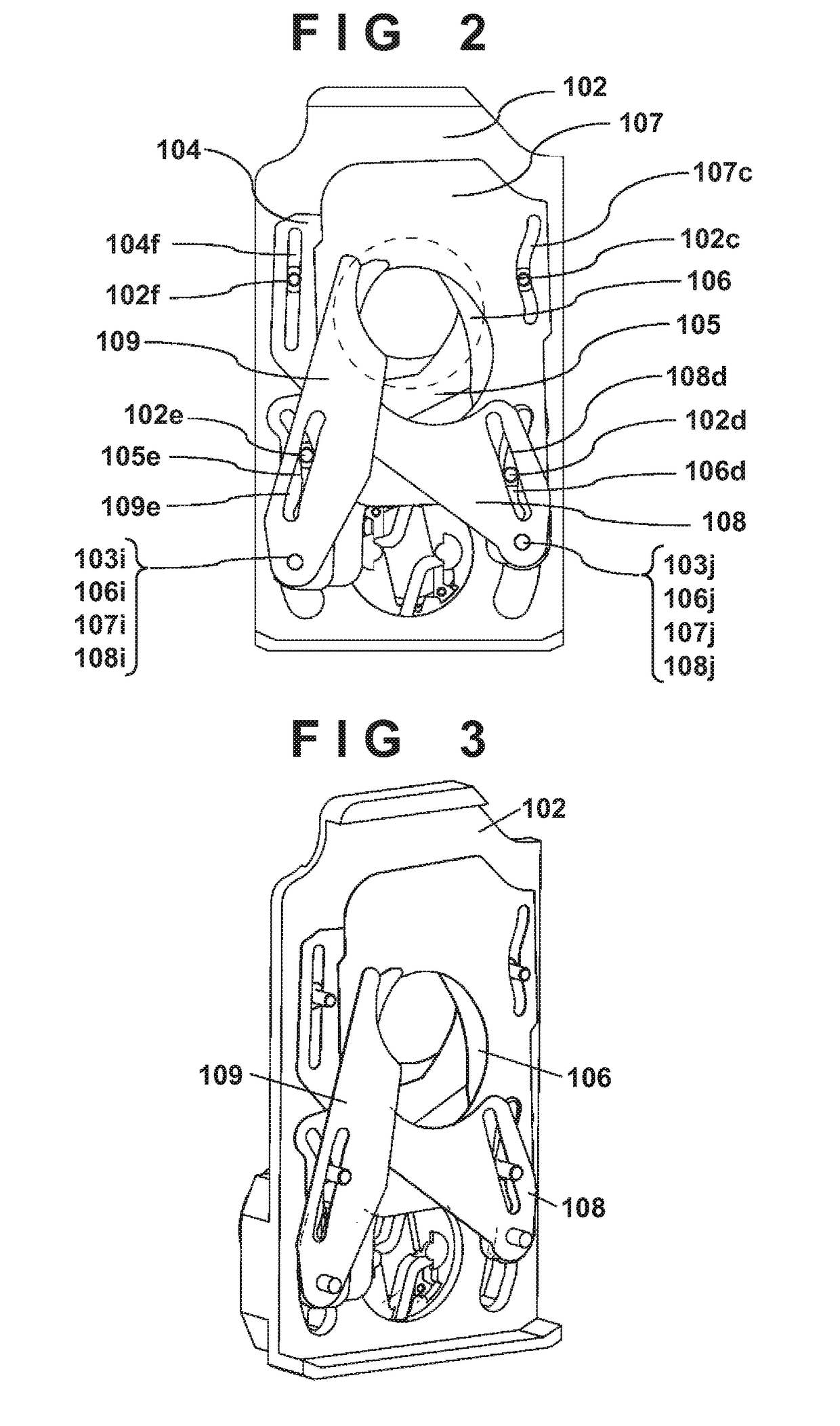
[0057]FIG. 1 is an exploded perspective view of a diaphragm device that is the first embodiment of a light amount adjusting device according to the present invention. FIG. 2 is a view showing the diaphragm device viewed from a direction (optical axis direction) in which light passes through a diaphragm opening formed by diaphragm blades (blade members) 104 to 109. Note that FIG. 2 shows a state in which a cover 110 shown in FIG. 1 is removed. FIG. 3 is a view showing the diaphragm device in FIG. 2, which is viewed obliquely. Additionally, in these drawings, the vertical direction of the diaphragm device, which is the longitudinal direction, corresponds to the “direction orthogonal to the light passing direction”, and this direction will be referred to as an optical axis orthogonal direction in the following explanation. In addition, the left-right direction of the diaphragm device in these drawings will be referred to as a width direction hereinafter.
[0058]Referring to FIGS. 1 to 3,...
second embodiment
[0103]FIG. 8 is an exploded perspective view of a diaphragm device that is the second embodiment of a light amount adjusting device according to the present invention. FIG. 9 is a front view of a pair of straight blades according to the second embodiment.
[0104]A diaphragm blade 204 and a diaphragm blade 207 form a pair of straight blades and move linearly in a direction orthogonal to a light passing opening to sandwich a fixed opening 202b of a base plate 202.
[0105]In the diaphragm blade 204, a long hole 204i engages with a blade drive pin 203i of a drive lever 203, a long hole 204e engages with a guide pin 202e of the base plate 202, and a long hole 204f engages with a guide pin 202f of the base plate. When the drive lever 203 is made to pivot, the diaphragm blade 204 receives a force from the blade drive pin 203i and actuates. The diaphragm blade 204 linearly moves toward the fixed opening 202b because its moving direction is guided by the two guide pins 202e and 202f.
[0106]In th...
third embodiment
[0115]FIG. 12 is an exploded perspective view of a diaphragm device that is the third embodiment of a light amount adjusting device according to the present invention. FIG. 13 is a front view of a third blade pair according to the third embodiment. A diaphragm blade 306 and a diaphragm blade 308 form a third diaphragm blade pair.
[0116]The diaphragm blade 306 slidably engages with a blade drive pin 303j of a drive lever 303 in a drive cam groove portion 306j. In addition, a rotation center pin 302d serving as a rotation center portion (rotation center axis portion) formed on a base plate 302 rotatably engages with a rotation center hole portion 306d that is an engaging portion formed in the diaphragm blade 306.
[0117]When the drive lever 303 pivots within a predetermined angle range, the drive cam groove portion 306j receives the driving force from the blade drive pin 303j, and the diaphragm blade 306 rotates (turns) in an optical axis orthogonal plane about the rotation center pin 30...
PUM
 Abstract
Description
Claims
Application Information
 - R&D
- Intellectual Property
- Life Sciences
- Materials
- Tech Scout
- Unparalleled Data Quality
- Higher Quality Content
- 60% Fewer Hallucinations
Browse by: Latest US Patents, China's latest patents, Technical Efficacy Thesaurus, Application Domain, Technology Topic, Popular Technical Reports.
© 2025 PatSnap. All rights reserved.Legal|Privacy policy|Modern Slavery Act Transparency Statement|Sitemap|About US| Contact US: help@patsnap.com


