
Exhaust gas purifying apparatus

a technology of exhaust gas and purification apparatus, which is applied in the direction of mechanical apparatus, engine components, machines/engines, etc., can solve the problems of reducing the purification performance of exhaust gas, affecting the purification efficiency of exhaust gas, so as to achieve the effect of reducing the temperature of the first catalyst, facilitating the flow and increasing the flow velocity of exhaust gas through the second gas passage portion

Active Publication Date: 2019-01-17
TOYOTA JIDOSHA KK
View PDF0 Cites 0 Cited by
  • Summary
  • Abstract
  • Description
  • Claims
  • Application Information

AI Technical Summary

Benefits of technology

This patent is about a new exhaust gas purifying system for engines that helps to increase the efficiency of purifying exhaust gas in an early stage after starting the engine. The system includes two catalysts, with the first catalyst having a low heat capacity to absorb less heat from the exhaust gas and allow it to flow towards the second catalyst, which has a higher heat capacity to quickly activate and purify the exhaust gas. This setup also helps to avoid excessive heat loss from the exhaust gas, which can delay the activation of the second catalyst and reduce purification efficiency. By increasing the heat capacity of the first catalyst and optimizing the flow of exhaust gas, the system can achieve higher purification efficiency earlier after starting the engine.

Problems solved by technology

Consequently, it takes a longer time to activate the second catalyst after the engine is started, which results in a longer time until the predetermined purification efficiency is reached from the time of starting the engine than when the first catalyst is not provided.
So far, it has been considered that when the heat capacity of a catalyst is set extremely low, the size of the catalyst becomes extremely small, and thus that almost zero exhaust gas purification performance will be obtained.
In addition, since the heat of exhaust gas passing through the first catalyst is difficult to be taken away by the first catalyst, the temperature of the second catalyst can also be increased in an early stage following the first catalyst due to the heat of the exhaust gas having passed through the first catalyst.
Therefore, in such a case, the effect of increasing the temperature of the second catalyst may not be fully expected.
Accordingly, the effect of increasing the temperature of the second catalyst may not be fully expected.

Method used


Image

  • Exhaust gas purifying apparatus
  • Exhaust gas purifying apparatus
  • Exhaust gas purifying apparatus

Examples


first embodiment

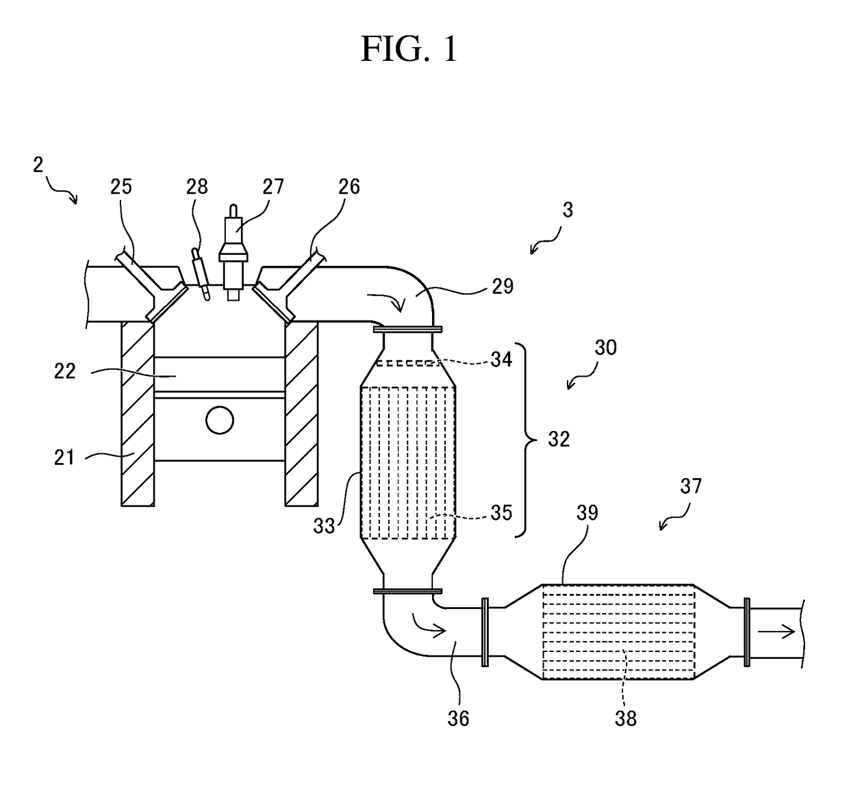
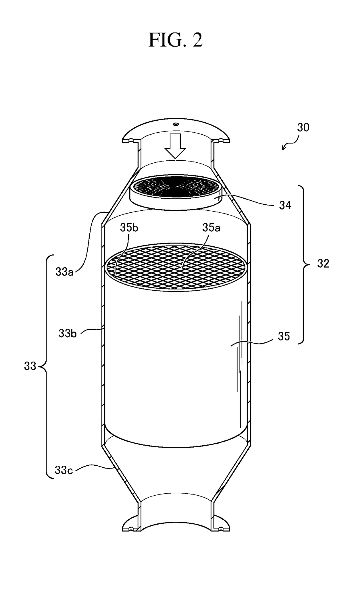
[0032]Hereinafter, an exhaust gas purifying apparatus in accordance with the first embodiment of the present disclosure will be described with reference to FIGS. 1 and 2. FIG. 1 is a schematic conceptual view illustrating an exhaust gas purifying apparatus 3 in accordance with an embodiment of the present disclosure. FIG. 2 is a schematic perspective view of a first catalytic converter 30 of the exhaust gas purifying apparatus 3 illustrated in FIG. 1. It should be noted that in FIG. 2, a housing 33 is illustrated in a half-split state to clearly show the inside of the first catalytic converter 30.

[0033]As illustrated in FIG. 1, the exhaust gas purifying apparatus 3 in accordance with this embodiment is an apparatus attached to the downstream side of an engine 2 for purifying exhaust gas generated through combustion processes in the engine 2. The engine 2 may be either a gasoline engine or a diesel engine. In this embodiment, a gasoline direct injection engine is exemplarily illustra...

second embodiment

[0054]FIG. 4 is a schematic conceptual view for illustrating an exhaust gas purifying apparatus in accordance with a second embodiment of the present disclosure. FIG. 5 is a schematic plan view of a first catalyst 34A illustrated in FIG. 4. The exhaust gas purifying apparatus in accordance with the second embodiment differs from that in the first embodiment in the shape of the first catalyst 34A. Therefore, other members having the same functions as those of the catalyst purifying apparatus in accordance with the first embodiment are denoted by the same reference numerals, and the detailed description thereof will be omitted.

[0055]The first catalyst 34A in accordance with the second embodiment has a substrate (catalyst substrate) 34′ made of the aforementioned metal material and has supported thereon metal catalysts for purifying exhaust gas. The substrate 34′ has a disk-like shape, and includes a metal frame (outer peripheral portion) 34a and a ring-like inner peripheral portion 34...

example 1

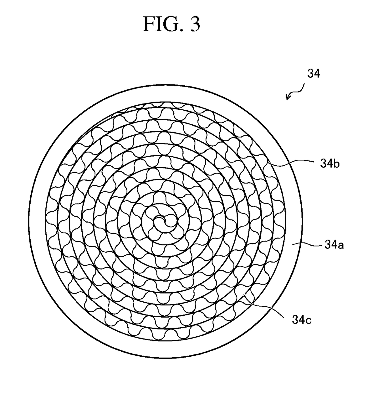
[0065]As illustrated below, the first catalytic converter 30 illustrated in FIG. 2 was produced. First, a substrate in the shape illustrated in FIG. 3 was prepared as the substrate (metal substrate) of the first catalyst 34. Specifically, the substrate of the first catalyst 34 was a disk-like substrate made of stainless steel (metal substrate) with a diameter of 80 mm and a length of 2 mm, the thickness of the ring-like metal frame (outer peripheral portion) 34a was 1.0 mm, the thickness of each of the wave-like metal band 34b and the plate-like metal band 34c was 30 μm, the number of cells per square inch was 600, and the weight of the substrate was 11.5 g.

[0066]Next, as metal catalysts, the substrate was coated with slurry of ceria-zirconia containing a predetermined percentage of rhodium particles, and was then dried at 120° C. and baked at 500° C. Accordingly, substrate was covered with a coat layer with a weight of 1.3 g, and the weight of rhodium therein was about 0.1 g.

[0067]...


PUM


Abstract

Provided is an exhaust gas purifying apparatus including a first catalyst and a second catalyst that passes exhaust gas from the first catalyst, in which the temperature of the second catalyst can be increased in an early stage after an engine is started, and thus exhaust gas purification efficiency can be enhanced in an earlier stage than in conventional apparatuses. The apparatus includes an exhaust gas purifying catalyst that includes a first catalyst for purifying exhaust gas from an exhaust manifold and a second catalyst for purifying exhaust gas having passed through the first catalyst. The heat capacity of the first catalyst is lower than that of the second catalyst. The heat capacity of the second catalyst is 184 to 322 J / K under a temperature environment of 25° C., and that of the first catalyst is less than or equal to 20 J / K under a temperature environment of 25° C.

Description

CROSS REFERENCE TO RELATED APPLICATIONS[0001]The present application claims priority from Japanese patent application JP 2018-045821 filed on Mar. 13, 2018 and Japanese patent application JP 2017-135619 filed on Jul. 11, 2017, the content of which is hereby incorporated by reference into this application.BACKGROUNDTechnical Field[0002]The present disclosure relates to an exhaust gas purifying apparatus including an exhaust gas catalyst for purifying exhaust gas from an exhaust manifold.Background Art[0003]Conventionally, an exhaust manifold is connected to an exhaust gas purifying apparatus for purifying exhaust gas discharged from an engine. The exhaust gas purifying apparatus includes a catalyst for purifying exhaust gas from the exhaust manifold, and the catalyst includes metal catalysts for purifying exhaust gas and a substrate (catalyst substrate) adapted to have the metal catalysts supported thereon.[0004]As such an exhaust gas purifying apparatus, for example, JP 2015-165095 ...

Claims


Application Information

Patent Timeline
Patent Type & Authority Applications(United States)
IPC IPC(8): F01N3/28F01N13/00F01N3/10F01N13/16
CPCF01N3/2803F01N13/0093F01N2330/02F01N13/16F01N2260/08F01N3/101F01N3/20F01N3/2006F01N3/2807F01N13/08Y02T10/12
Inventor ISHIKAWA, NORIO
Owner TOYOTA JIDOSHA KK
Learn More