
Virtual object display system

a virtual object and display system technology, applied in the field of virtual object display system, can solve the problems of impossible to distinguish markers, and problems such as the plurality of problems, and achieve the effect of simple methods

Inactive Publication Date: 2019-01-03
FANUC LTD
View PDF0 Cites 16 Cited by
  • Summary
  • Abstract
  • Description
  • Claims
  • Application Information

AI Technical Summary

Benefits of technology

The present invention is a system that can display virtual objects using a simple method. This means that the system can display virtual objects in a simple and easy way.

Problems solved by technology

However, when as shown in FIG. 29, the marker is arranged on the movable portion of the actual machine tool, there are a plurality of problems as shown in FIG. 30.
For example, there is a problem in which as shown as (30A) on the left of FIG. 30, it is likely that it is impossible to distinguish the marker.
This is because although in order to draw augmented information, it is necessary to capture the marker with a camera, it is likely that it is impossible to distinguish the marker as a result of the movement or rotation of the movable portion on which the marker is installed.
However, in the technology disclosed in Patent Document 4, since it is thereafter impossible to detect the movement of the marker arranged on the movable portion, the augmented information displayed is not moved after the marker cannot be distinguished.
Hence, even if the technology disclosed in Patent Document 4 is utilized, when the marker cannot be distinguished, it is impossible to perform appropriate machining simulation.
There is also a problem in which as shown as (30B) in the center of FIG. 30, it is likely that the moving speed of the movable portion is high, and thus recognition processing for the marker cannot catch up therewith.
There is also a problem in which as shown as (30C) on the right of FIG. 30, it is likely that the marker cannot be arranged on the movable portion in the first place.

Method used


Image

  • Virtual object display system
  • Virtual object display system
  • Virtual object display system

Examples


Embodiment Construction

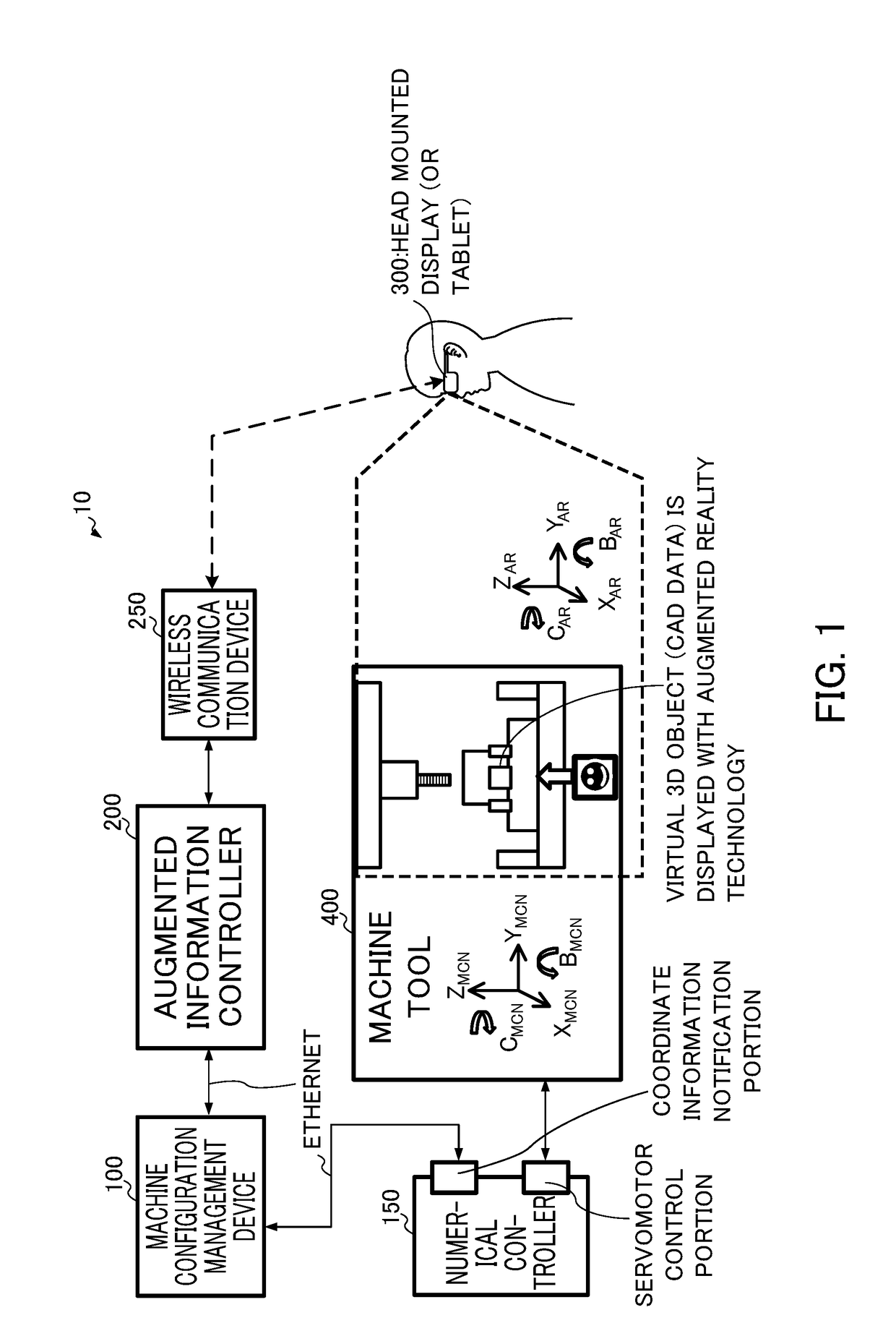
[0093]An embodiment of the present invention will then be described in detail with reference to drawings. The configuration of the entire present embodiment will first be described with reference to FIG. 1.

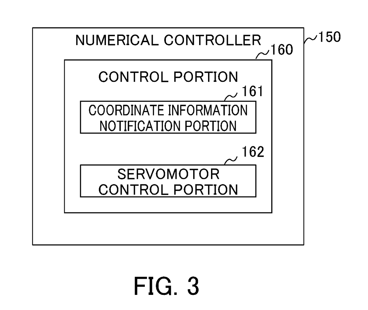
[0094]A virtual object display system 10 according to the present embodiment includes a machine configuration management device 100, a numerical controller 150, an augmented information controller 200, a wireless communication device 250, a head mounted display 300 and a machine tool 400.

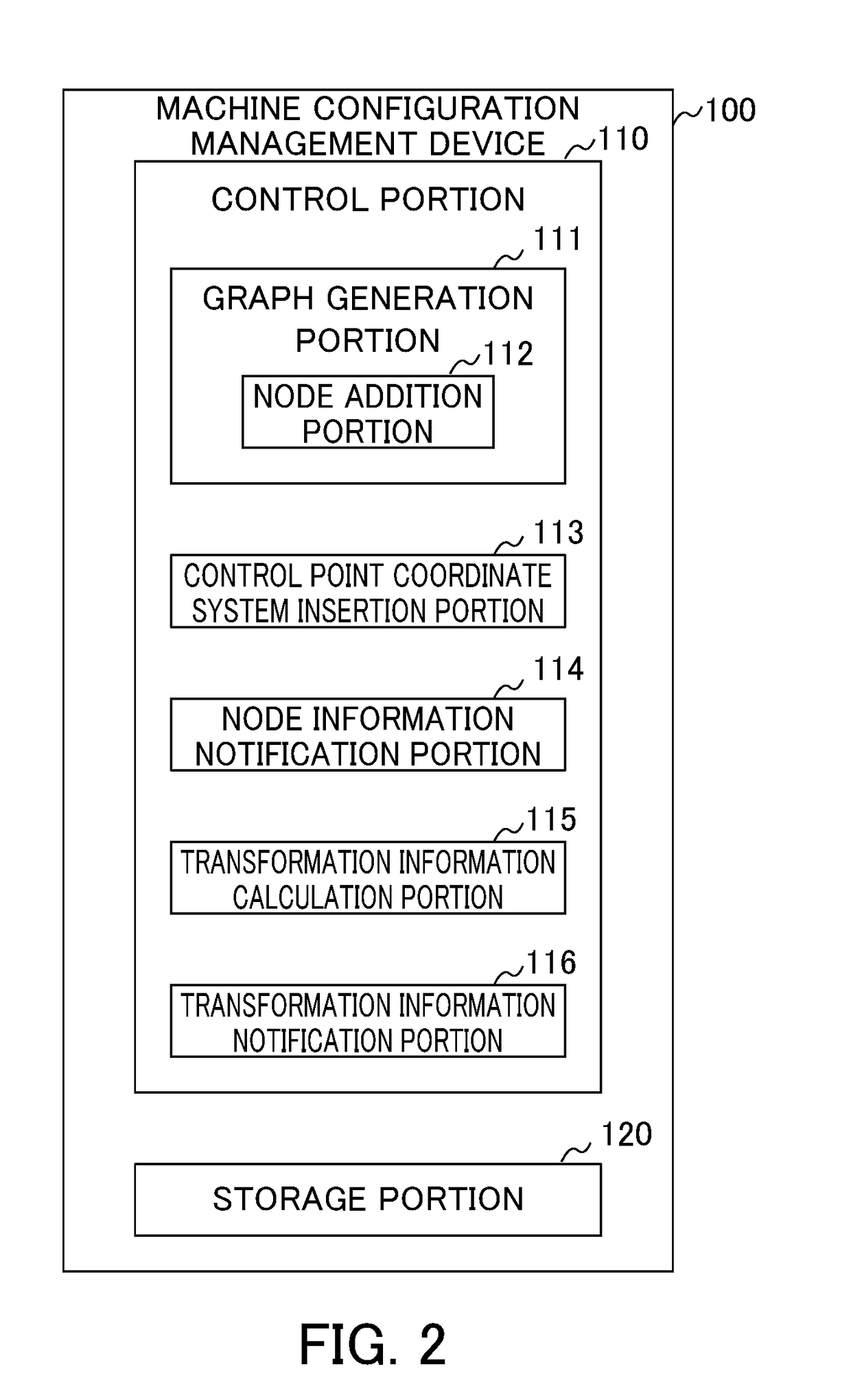
[0095]The machine configuration management device 100 is a device specific to the present embodiment, produces a graph (hereinafter also referred to as the “machine configuration tree”) in which the constituent elements of the machine tool 400 are nodes and uses the graph to manage a machine configuration, and thus the augmented information controller 200 which will be described later can perform control by utilization of data of the machine configuration based on the machine configuration tree.

[0...


PUM


Abstract

A virtual object display system that generates, as the machine configuration of a control target, a graph including nodes, selects a node on which a virtual object is to be displayed, notifies the node on which the virtual object is to be displayed to a machine configuration management device, calculates transformation information which includes a coordinate value of a control axis node on a path in the graph from a marker node to the node of a display target and which is used for calculating the position and / or the posture of the node of the display target in a coordinate system of the marker node based on the graph, notifies the transformation information to an augmented information controller and transforms the coordinate value of a control axis into the position and / or the posture of the node of the display target in the coordinate system of the marker node.

Description

[0001]This application is based on and claims the benefit of priority from Japanese Patent Application No. 2017-127692, filed on 29 Jun. 2017, the content of which is incorporated herein by reference.BACKGROUND OF THE INVENTIONField of the Invention[0002]The present invention relates to a virtual object display system for performing a simulation using the technology of AR (Augmented Reality) and MR (Mixed reality).Related Art[0003]Conventionally, in the field of machine tools controlled by numerical controllers, workpieces and fixtures are designed by CAD (computer-aided design) or the like. The designed fixture is used, and thus a machining program for machining the workpiece is produced. Then, the machine tool is controlled by the numerical controller based on the machining program, and thus the machining of the workpiece is realized.[0004]Here, before the fixture and the workpiece designed and the machining program are actually placed in a manufacturing line, in order to check if...

Claims


Application Information

Patent Timeline
Patent Type & Authority Applications(United States)
IPC IPC(8): G06T19/00G06T11/20G05B19/402
CPCG06T19/006G06T11/206G05B19/402G05B2219/39449G05B2219/31261G05B17/02G05B19/4069G06F30/17G06F30/20G06F2111/18
Inventor OONISHI, NOBUHITO
Owner FANUC LTD
Learn More