
Method for producing 2,3,3,3-tetrafluoropropene

a technology of tetrafluoropropene and tetrafluoropropene, which is applied in the field of production of 2, 3, 3, 3tetrafluoropropene, can solve the problems of inability to complete the recovery of refrigerants, inability to ignore diffusion of refrigerants due to leakage, and increase global warming of refrigerants, so as to achieve stably produced, suppress catalyst deactivation in the reaction system, and suppress the effect of deactivation

Inactive Publication Date: 2018-12-27
DAIKIN IND LTD
View PDF2 Cites 0 Cited by
  • Summary
  • Abstract
  • Description
  • Claims
  • Application Information

AI Technical Summary

Benefits of technology

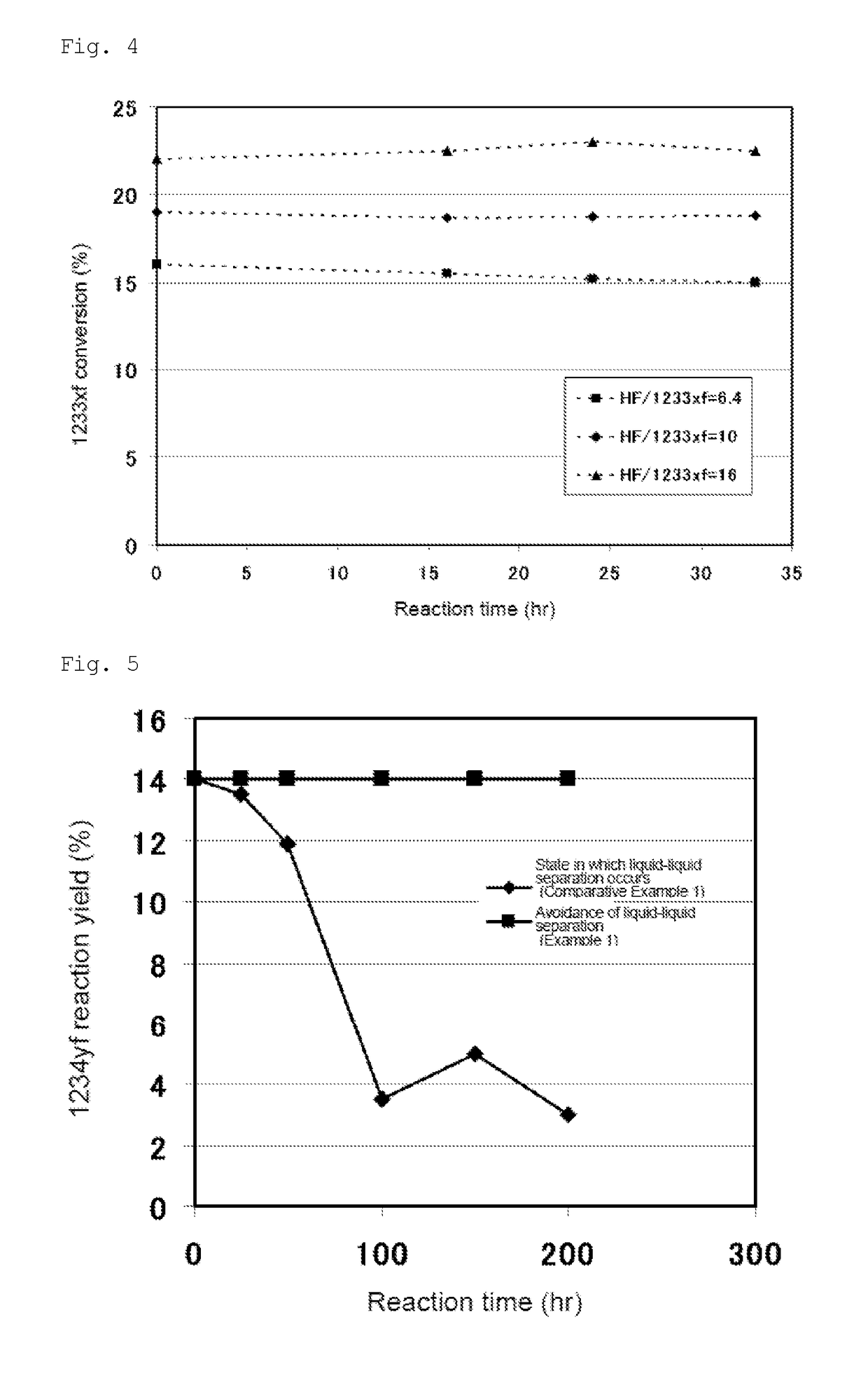
The present invention relates to a method for producing chloropropene and 2,3,3,3-tetrafluoropropene. The method involves a distillation process where the reaction mixture containing unreacted starting materials and unreacted hydrogen fluoride is not separated. This fraction is then reused in the reaction, resulting in the stable production of chloropropene and 2,3,3,3-tetrafluoropropene for a long period of time without catalyst deactivation. The technical effect of the invention is the suppression of catalyst deactivation in the reaction system and the stable production of chloropropene and 2,3,3,3-tetrafluoropropene.

Problems solved by technology

However, these alternative refrigerants are potent global warming substances, thus creating concern that diffusion of the refrigerants would increase global warming.
However, complete recovery of the refrigerants is impossible.
In addition, diffusion of these refrigerants due to, for example, leakage, cannot be ignored.
However, because CO2 refrigerants have low efficiency, and devices using such refrigerants inevitably become large, CO2 refrigerants have many problems in terms of the overall reduction of greenhouse gas emissions, including energy to be consumed.
Furthermore, hydrocarbon-based substances pose safety problems due to their high flammability.

Method used


Image

  • Method for producing 2,3,3,3-tetrafluoropropene
  • Method for producing 2,3,3,3-tetrafluoropropene
  • Method for producing 2,3,3,3-tetrafluoropropene

Examples


example 1

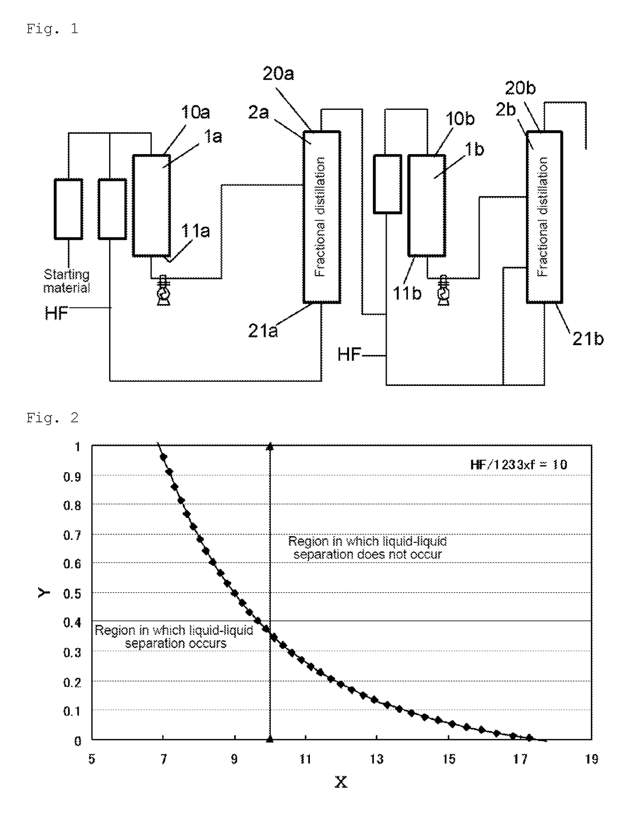
[0121]HFO-1234yf was produced according to the production flow shown in FIG. 1. Cylinder-shaped reactors made of Hastelloy C22 were used. Cylinder-shaped packed columns made of Hastelloy C22 were used as distillation columns. The packing used was CMRNo2.5, the column diameter was 500 A, and the packed length was 10000 mm×2.

[0122]240db (1,1,1,2,3-pentachloropropane) was used as a starting material in step (a) of the first stage. A mixed gas of 240db and hydrogen fluoride was continuously supplied to a first reactor 1a at a flow rate of 7,000 m3 / hr (in terms of standard conditions for gas). The internal temperature of the first reactor 1a was 300° C., and the pressure was 0.75 MPa (gauge pressure). Further, in the reaction, the molar ratio of hydrogen fluoride to 240db was 20. To the first reactor 1a, 24.8 t of a Cr oxide catalyst (Cr2O3) was supplied as a catalyst in advance.

[0123]After the reaction, the reaction products were withdrawn from the first reactor 1a, fed to a first disti...

example 2

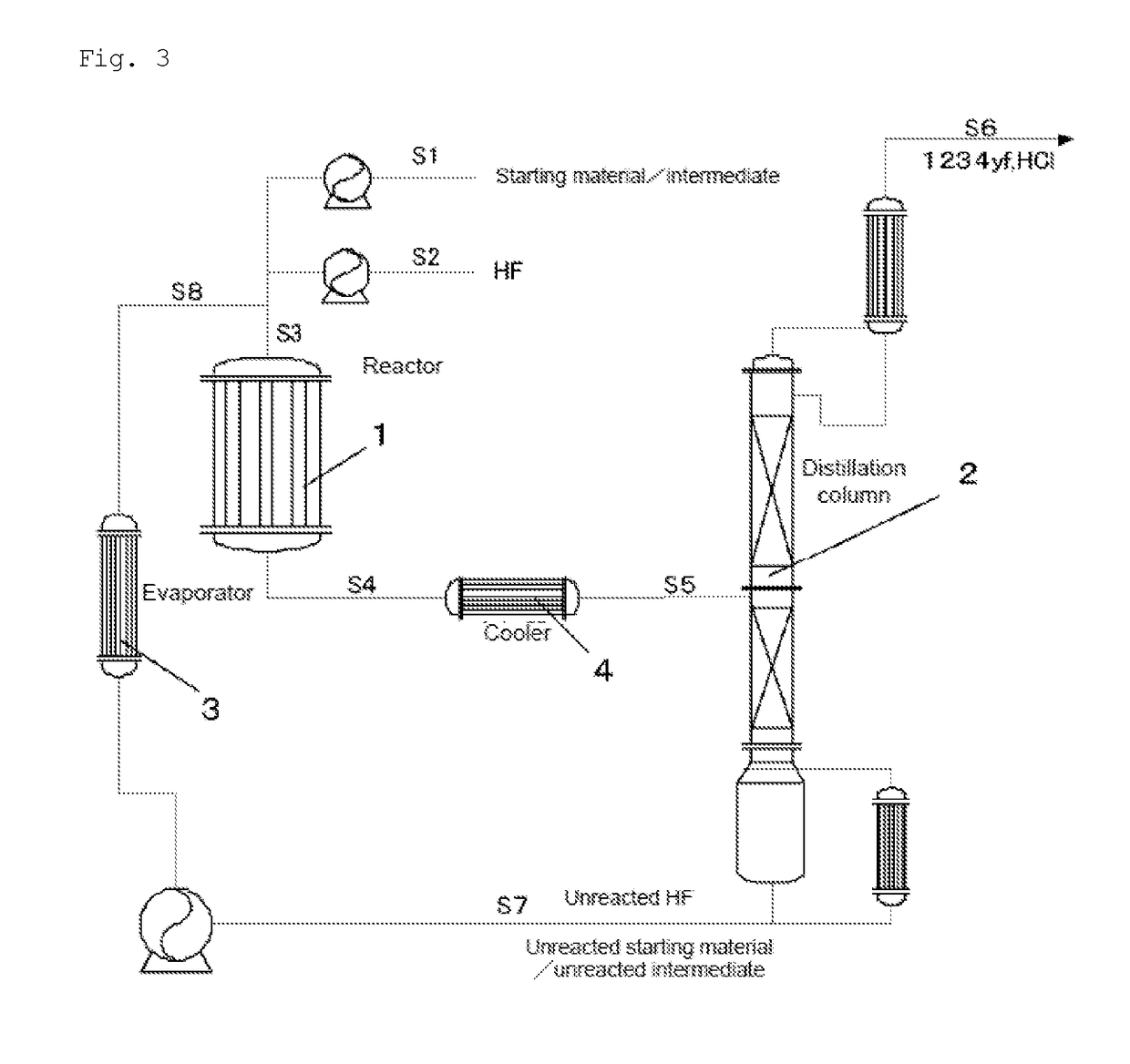
[0128]1233xf was produced from 240db according to the production flow shown in FIG. 3. First, 240db was fed through the S1 line, hydrogen fluoride was fed through the S2 line, and these two came together in the S3 line. The mixed gas of 240db and hydrogen fluoride was continuously supplied to a reactor 1 at a flow rate of 7,000 m3 / hr (in terms of standard conditions for gas). The internal temperature of the reactor 1 was 300° C., and the pressure was 0.75 MPa (gauge pressure). Further, in this reaction, the molar ratio of hydrogen fluoride to 240db was 20. To the reactor 1, 24.8 t of a Cr oxide catalyst (Cr2O3) was supplied as a catalyst in advance. After the reaction, the reaction mixture was withdrawn from the reactor 1, fed to a distillation column 2, and subjected to distillation. The same reactor, distillation column, evaporator, and cooler as used in Example 1 were used for the reactor 1, distillation column 2, evaporator 3, and cooler 4.

[0129]The distillation in the distillat...

example 3

[0131]1233xf was produced from 1230xa (1,1,2,3-tetrachloropropene) according to the production flow shown in FIG. 3. First, 1230xa was fed through the S1 line, hydrogen fluoride was fed through the S2 line, and these two came together in the S3 line. The mixed gas of 1230xa and hydrogen fluoride was continuously supplied to a reactor 1 at a flow rate of 7,000 m3 / hr (in terms of standard conditions for gas). The internal temperature of the reactor 1 was 300° C., and the pressure was 0.75 MPa. Further, in this reaction, the molar ratio of hydrogen fluoride to 1230xa was 20. To the reactor 1, 24.8 t of a Cr oxide catalyst (Cr2O3) was supplied as a catalyst in advance. After the reaction, the reaction mixture was withdrawn from the reactor 1, fed to a distillation column 2, and subjected to distillation. The unreacted 1230xa and the unreacted hydrogen fluoride were withdrawn from the still of the distillation column 2 and fed to the reactor 1 again to be reused as raw materials for the ...


PUM

PropertyMeasurementUnit
pressureaaaaaaaaaa
pressureaaaaaaaaaa
molar ratioaaaaaaaaaa

Abstract

This invention provides a method for stably producing 2,3,3,3-tetrafluoropropene for a long period of time while suppressing catalyst deactivation. This invention provides a method for producing 2,3,3,3-tetrafluoropropene, the method comprising: (d) reacting 2-chloro-3,3,3-trifluoropropene with hydrogen fluoride in the presence of a catalyst; (e) subjecting the reaction mixture obtained in step (d) to distillation to separate the mixture into a first stream comprising 2,3,3,3-tetrafluoropropene as a main component and a second stream comprising unreacted hydrogen fluoride and organic matter containing unreacted 2-chloro-3,3,3-trifluoropropene as main components; and (f) recycling the second stream separated in step (e) above to the reaction of step (d), wherein the distillation of step (e) is performed under conditions that satisfy the relationship of a specific equation.

Description

TECHNICAL FIELD[0001]The present invention relates to a method for producing 2,3,3,3-tetrafluoropropene.BACKGROUND ART[0002]Alternative refrigerants, such as HFC-125(C2HF5) and HFC-32(CH2F2), have been widely used as important replacements for CFC, HCFC, etc., which cause ozone layer depletion. However, these alternative refrigerants are potent global warming substances, thus creating concern that diffusion of the refrigerants would increase global warming. As a preventive measure, these refrigerants are recovered after use. However, complete recovery of the refrigerants is impossible. In addition, diffusion of these refrigerants due to, for example, leakage, cannot be ignored. The use of CO2 or hydrocarbon-based substances as alternative refrigerants has also been investigated. However, because CO2 refrigerants have low efficiency, and devices using such refrigerants inevitably become large, CO2 refrigerants have many problems in terms of the overall reduction of greenhouse gas emi...

Claims


Application Information

Patent Timeline
Patent Type & Authority Applications(United States)
IPC IPC(8): C07C17/087C07C17/383
CPCC07C17/087C07C17/383C07B61/00C07C17/25Y02P20/582C07C17/206C07C21/18
Inventor TAKAKUWA, TATSUYATAKAHASHI, KAZUHIROKARUBE, DAISUKECHAKI, TAKEHIROKISHIMOTO, MASAYUKIKOMATSU, YUZO
Owner DAIKIN IND LTD
Learn More