
Method and facility for filling a gas-insulated electrical apparatus comprising a mixture of (CF3)2cfcn and co2

a gas-insulated electrical apparatus and mixture technology, applied in the field of electric insulation and electric arc, can solve the problems of low gas-insulated equipment price, no simple means, and strong greenhouse gas emission

Active Publication Date: 2018-12-13
GENERAL ELECTRIC TECH GMBH
View PDF14 Cites 21 Cited by
  • Summary
  • Abstract
  • Description
  • Claims
  • Application Information

AI Technical Summary

Benefits of technology

The present invention provides a method and apparatus for filling high- or medium-voltage equipment with a gas mixture containing heptafluoroisobutyronitrile and carbon dioxide. This technique allows for accurate and stable transfer of the gas mixture, regardless of the initial ratio of components or external temperature. The insulating medium used in the equipment can be made into a stable liquid for space-saving purposes, and can be conveniently returned to a gaseous state for use again. The technical effect is an improved and reliable insulation and extinction of electric arcs in high- and medium-voltage equipment.

Problems solved by technology

In addition, it is non-flammable and its price is still moderate.
However, SF6 has the major disadvantage of presenting a global warming potential (GWP) of 23 500 (relative to carbon dioxide (CO2) over 100 years) and a time period spent in the atmosphere of 3200 years, which places it among very strong greenhouse gases.
For the moment, no simple means exist for making it possible to fill high- or medium-voltage equipment with a gas mixture comprising at least two distinct components such as a mixture of heptafluoroisobutyronitrile and carbon dioxide: all current methods of filling present one or more drawbacks.
The drawback of that method is that it requires two separate containers to be manipulated and that the mixture created is not immediately homogeneous and therefore takes time to become homogenized.
That implementation is complex and may lead to errors of implementation on site if the partial pressures of each component are not complied with.
Another filling method uses a gas mixer, but this implementation is complex and relies on the use of expensive gas mixers.
That implementation suffers from the non-stability of the ratio between the two components as a function of the filling rate of the bottle.

Method used


Image

  • Method and facility for filling a gas-insulated electrical apparatus comprising a mixture of (CF3)2cfcn and co2
  • Method and facility for filling a gas-insulated electrical apparatus comprising a mixture of (CF3)2cfcn and co2

Examples


Embodiment Construction

[0055]Above and below, the expression “high voltage” is used in the conventionally accepted manner, i.e. the expression “high voltage” refers to a voltage that is strictly greater than 52,000 volts (V) for alternating current (AC) and 75,000 volts for direct current (DC).

[0056]In the context of the invention, the expression “medium voltage” is used in the conventionally accepted manner, i.e. the term “medium voltage” refers to a voltage that is greater than 1000 V for AC or greater than 1500 V for DC, but that does not exceed 52,000 V for AC, or 75,000 V for DC.

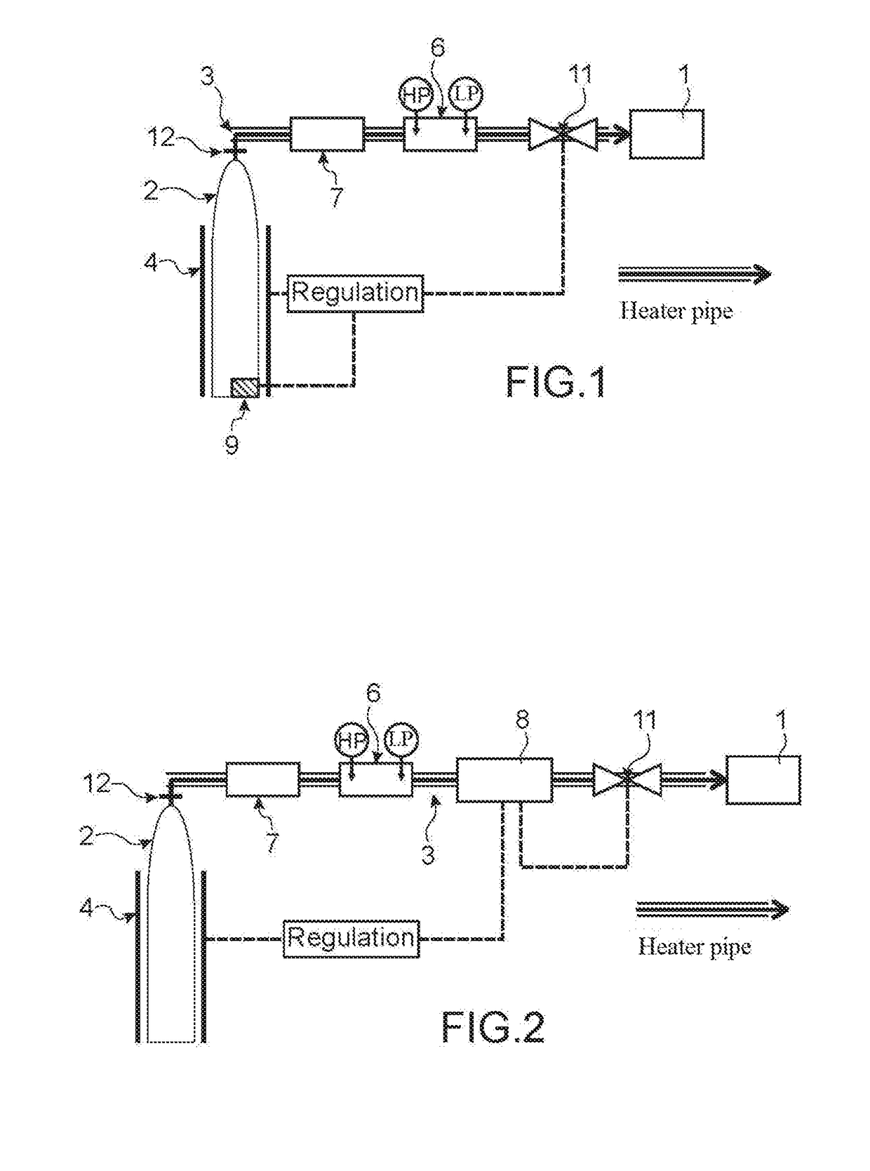
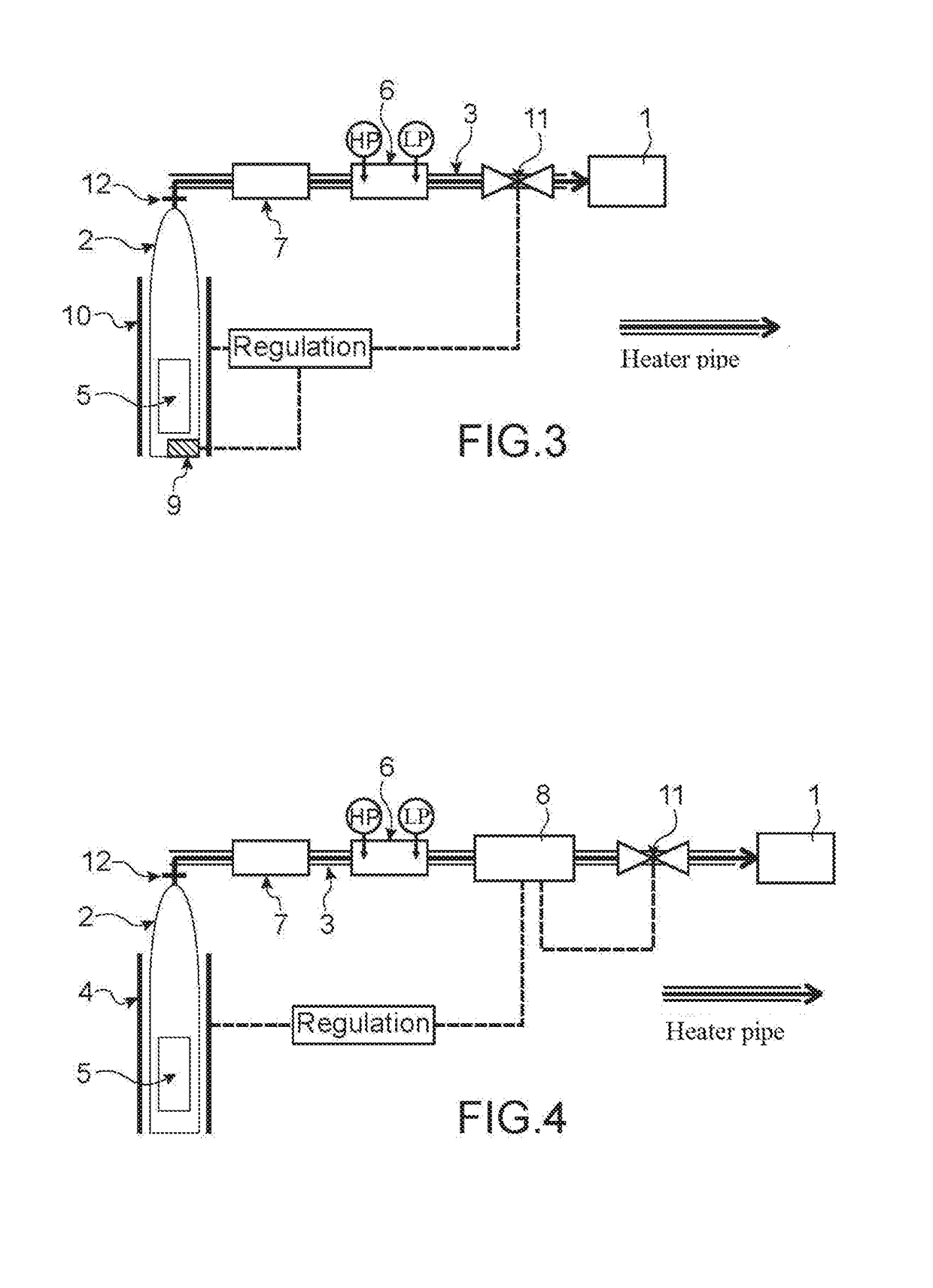
[0057]An electrical apparatus mainly comprises a longitudinal outer casing or enclosure (1), defining a hollow volume and one or more electrical component(s) that is / are arranged inside the casing.

[0058]The inside volume of the casing is closed in gastight manner and is filled with a gas for electrical insulation and for electric arc extinction, which gas comprises a mixture of heptafluoroisobutyronitrile and carbon dioxide.

[...


PUM

PropertyMeasurementUnit
GWPaaaaaaaaaa
critical temperatureaaaaaaaaaa

Abstract

A method and a facility for filling a high- or medium-voltage gas-insulated electrical apparatus in which the insulating gas comprises a mixture of heptafluoroisobutyronitrile ((CF3)2CFCN) and carbon dioxide. The method and the facility using a mixture of (CF3)2CFCN and CO2 in pressurised liquid form which is heated to a temperature no lower than the critical temperature of the mixture.

Description

TECHNICAL FIELD[0001]The invention relates to the field of electrical insulation and electric arc extinction in high- or medium-voltage equipment.[0002]More particularly, the present invention relates to a method and an installation for filling gas-insulated high- or medium-voltage equipment for which the insulation gas comprises a mixture of heptafluoroisobutyronitrile ((CF3)2CFCN) and carbon dioxide.STATE OF THE PRIOR ART[0003]In equipment for a transmission line carrying high- or medium-voltage electricity, the functions of electrical insulation and of electric arc extinction are typically performed by a gas that is confined to the inside of the equipment.[0004]Currently, sulfur hexafluoride (SF6) is the most frequently used gas. That gas presents dielectric strength that is relatively high, good thermal conductivity, and low dielectric losses. It is chemically inert, non-toxic for humans and animals and, after being dissociated by an electric arc, it recombines quickly and almos...

Claims


Application Information

Patent Timeline
Patent Type & Authority Applications(United States)
IPC IPC(8): H01B3/56F17C5/06H01H33/56
CPCH01B3/56F17C5/06H01H33/562H01H2033/566H02B13/055H01H33/56G05D16/20G05D16/02G05D16/2013H01H33/563F17C2227/0304H01H2033/568F17C13/028F17C2227/0325
Inventor KIEFFEL, YANNICKBIQUEZ, FRANCOISPORTE, JACQUES
Owner GENERAL ELECTRIC TECH GMBH
Learn More