Bidirectional coupler, monitor circuit, and front end circuit
a monitor circuit and bidirectional coupler technology, applied in the direction of electrical equipment, coupling devices, transmission, etc., can solve the problems of inequivalence between the directivity of a forward direction signal and a reverse direction signal, and achieve the effect of high accuracy
- Summary
- Abstract
- Description
- Claims
- Application Information
AI Technical Summary
Benefits of technology
Problems solved by technology
Method used
Image
Examples
first embodiment
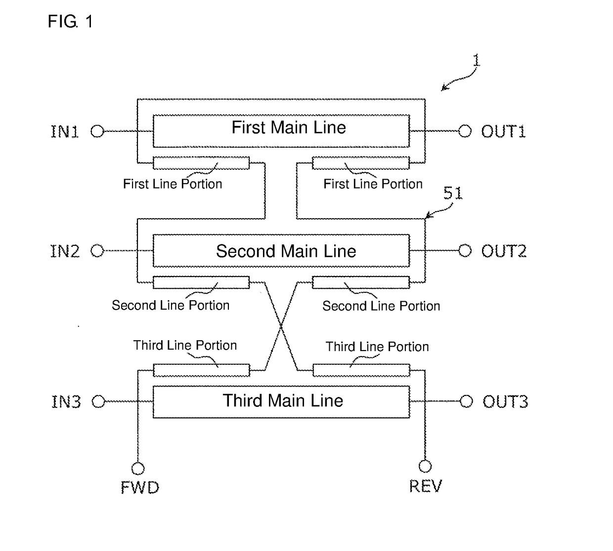
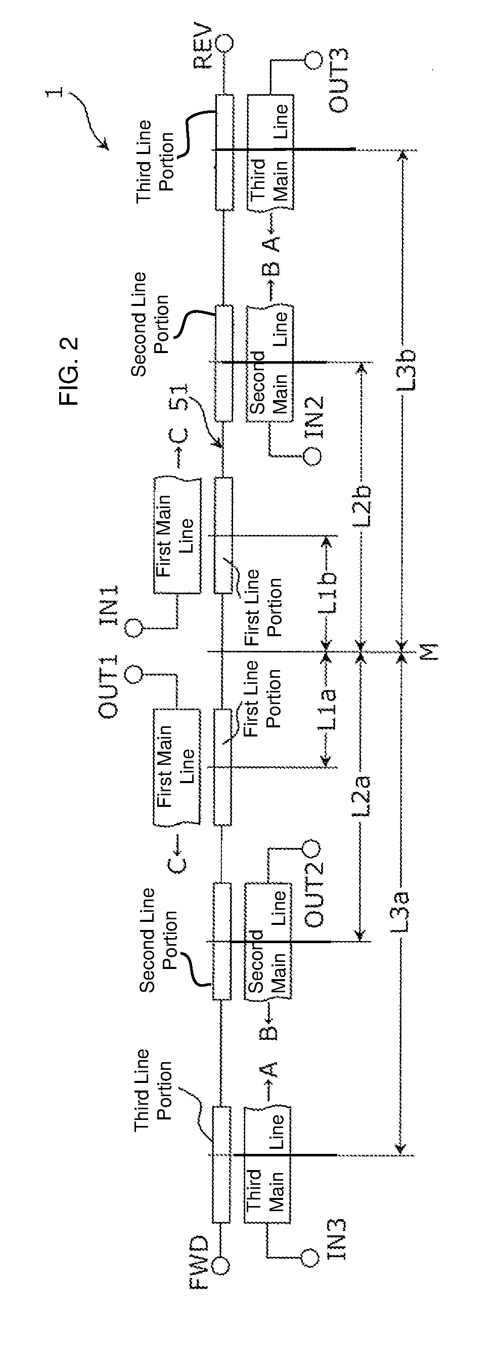
[0070]FIG. 1 is a circuit diagram that illustrates an example of an equivalent circuit of a bidirectional coupler 1 according to a first embodiment.
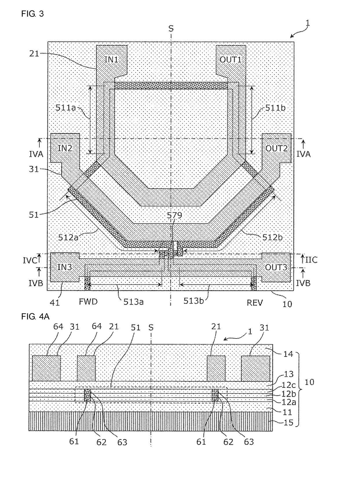
[0071]As illustrated in FIG. 1, the bidirectional coupler 1 includes a first main line 21, a second main line 31, a third main line 41, and a sub line 51.
[0072]A first end and a second end of the first main line 21 constitute an input port IN1 and an output port OUT1, a first end and a second end of the second main line 31 constitute an input port IN2 and an output port OUT2, and a first end and a second end of the third main line 41 constitute an input port IN3 and an output port OUT3. A first end and a second end of the sub line 51 constitute a forward port FWD and a reverse port REV.
[0073]The sub line 51 includes a pair of first line portions 511a and 511b coupled to the first main line 21, a pair of second line portions 512a and 512b coupled to the second main line 31, and a pair of third line portions 513a and 513b coupled to the th...
second embodiment
[0101]In a second embodiment, variations of the first main line, the second main line, the third main line, and the sub line are described.
[0102]FIG. 6 is a circuit diagram that illustrates an example of an equivalent circuit of a bidirectional coupler 2.
[0103]As illustrated in FIG. 6, the bidirectional coupler 2 includes a first main line 22, a second main line 32, a third main line 42, and a sub line 52.
[0104]A first end and a second end of the first main line 22 constitute an input port IN1 and an output port OUT1, a first end and a second end of the second main line 32 constitute an input port IN2 and an output port OUT2, and a first end and a second end of the third main line 42 constitute an input port IN3 and an output port OUT3. A first end and a second end of the sub line 52 constitute a forward port FWD and a reverse port REV.
[0105]The sub line 52 includes a pair of first line portions 521a and 521b, each coupled to the first main line 22, a pair of second line portions 52...
third embodiment
[0120]In a third embodiment, variations of the first main line, the second main line, the third main line, and the sub line are described.
[0121]FIG. 8 is a circuit diagram that illustrates an example of an equivalent circuit of a bidirectional coupler 3.
[0122]As illustrated in FIG. 8, the bidirectional coupler 3 includes a first main line 23, a second main line 33, a third main line 43, and a sub line 53.
[0123]A first end and a second end of the first main line 23 constitute an input port IN1 and an output port OUT1, a first end and a second end of the second main line 33 constitute an input port IN2 and an output port OUT2, and a first end and a second end of the third main line 43 constitute an input port IN3 and an output port OUT3. A first end and a second end of the sub line 53 constitute a forward port FWD and a reverse port REV.
[0124]The sub line 53 includes a pair of first line portions 531a and 531b, which become coupled to the first main line 23, a pair of second line port...
PUM
 Abstract
Description
Claims
Application Information
 - R&D
- Intellectual Property
- Life Sciences
- Materials
- Tech Scout
- Unparalleled Data Quality
- Higher Quality Content
- 60% Fewer Hallucinations
Browse by: Latest US Patents, China's latest patents, Technical Efficacy Thesaurus, Application Domain, Technology Topic, Popular Technical Reports.
© 2025 PatSnap. All rights reserved.Legal|Privacy policy|Modern Slavery Act Transparency Statement|Sitemap|About US| Contact US: help@patsnap.com


