Uniflow engine with intake and/or exhaust valves

Active Publication Date: 2018-11-15
VOLVO LASTVAGNAR AB
View PDF5 Cites 0 Cited by
  • Summary
  • Abstract
  • Description
  • Claims
  • Application Information

AI Technical Summary

Benefits of technology

The patent text discusses the challenges in optimizing the scavenging process in two-stroke engines and the difficulty in achieving the same level of conversion efficiency as in conventional single piston engines. The text proposes a solution to improve the efficiency of opposed piston engines by aligning the motion of the pistons with the combustion pressure rise and providing a different solution for port timing to achieve the same scavenging performance. The technical effects of this solution include reducing efficiency losses and achieving higher engine output.

Problems solved by technology

While ports are advantageous in allowing a larger flow area than can be accomplished with poppet valves, they have the disadvantage that opening and closing times result from the motion of the piston, and are symmetric about the piston bottom dead center.
This location inherently achieves “uniflow-scavanging”, which provides an advantage for optimal scavenging by separating the intake and exhaust as much as possible, thereby reducing mixing of the fresh and burnt gases, but the use of pistons to control both ports creates a difficulty in timing the opening and closing of the ports to also achieve good scavenging.
These two conditions are difficult to achieve in a two-stroke cycle, where a single piston may control both ports.
However, this design requires a valve train system very similar to that of a four-stroke engine, which reduces the potential cost advantage of a two-stroke engine, and the achievable flow area of the poppet valves may restrict the exhaust flow.
When the two pistons of an opposed piston engine are phased, the best combustion timing will be somewhat late for the leading piston, but will be too early for the trailing piston, with a large amount of the pressure rise trying to push that piston in the reverse direction.
This results in high torsional vibration, and also significant periods of “negative torque” of the trailing crankshaft during the cycle, which subtracts from the positive torque of the leading crankshaft, resulting in lower than expected engine output.

Method used


Image

  • Uniflow engine with intake and/or exhaust valves
  • Uniflow engine with intake and/or exhaust valves
  • Uniflow engine with intake and/or exhaust valves

Examples


Embodiment Construction

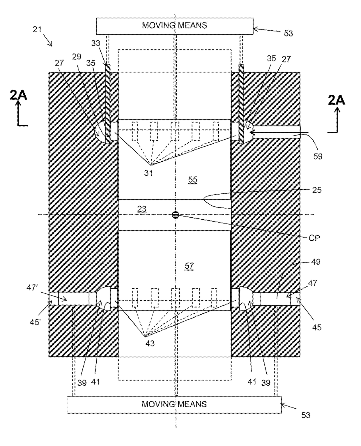
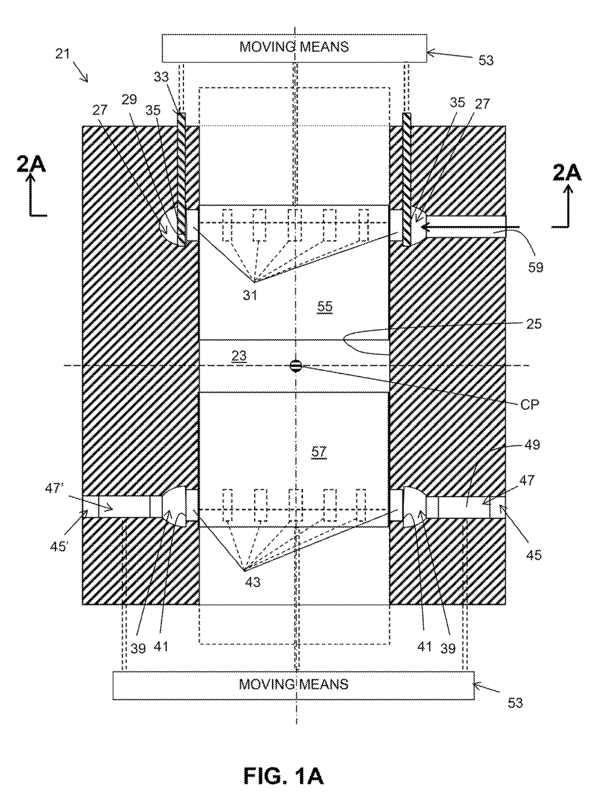
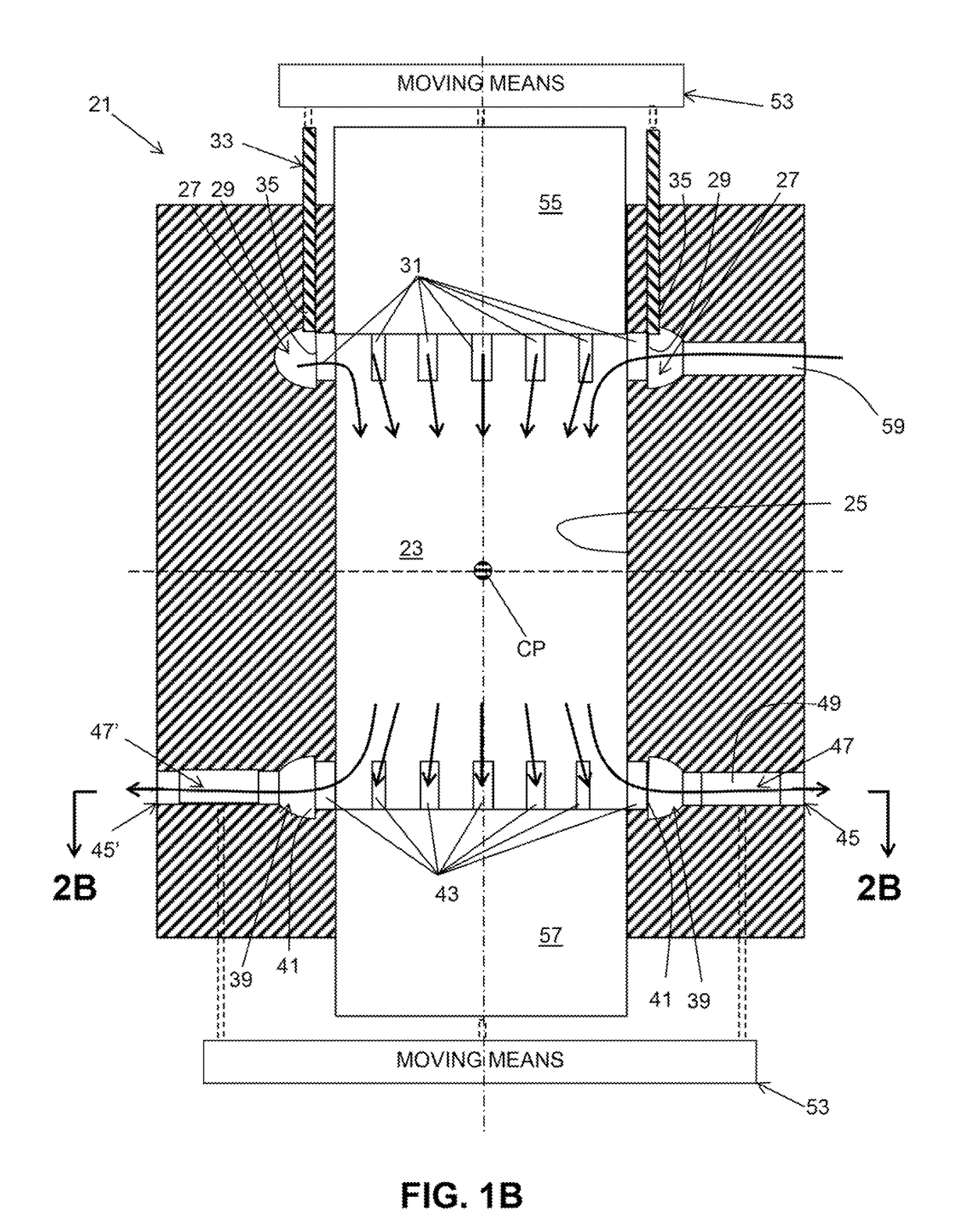
[0024]FIGS. 1A-2C show a uniflow engine 21 according to, an aspect of the present invention (FIG. 2D shows a portion of a modified design of a uniflow engine). The illustrated engine 21 is an opposed piston engine and is described for purposes of discussion and to explain features of the invention, however, it will be appreciated that aspects of the invention are also applicable to non-opposed piston, uniflow engines. In general, an engine according to an aspect of the invention comprises a cylinder having a cylinder wall, a volume exterior to the cylinder, at least one channel extending between the cylinder wall and the volume, and a valve outside of the cylinder configured to open and close flow communication between the cylinder and the volume through the channel.

[0025]In an aspect of the invention, the engine 21 comprises a cylinder 23 having a cylinder wall 25, an intake air gallery 27, the intake air gallery having an intake air gallery wall 29, at least one intake port 31 ext...


PUM


Abstract

A uniflow engine includes a cylinder having a cylinder wall, a volume exterior to the cylinder, at least one channel extending between the cylinder wall and the volume, and a valve outside of the cylinder configured to open and close flow communication between the cylinder and the volume through the channel.

Description

BACKGROUND AND SUMMARY[0001]The present invention relates generally to uniflow engines and, more particularly, to arrangements for scavenging of such engines.[0002]Two-stroke engines are often categorized by the method by which they achieve gas exchange, i.e., the process of expelling burned gases from a cylinder after combustion and of refilling the cylinder with a fresh charge, e.g. fresh air or a mixture of fresh air and, e.g., fuel. In the field of two-stroke engines, this is called scavenging. Known scavenging designs include cross-, loop-, and uniflow scavenging. Unlike in four-stroke engines, the entire two-stroke scavenging process occurs simultaneously when the piston or pistons are at or near their outermost (bottom dead center) position, and is driven by some external pumping device and not by the motion of the pistons between bottom dead center and top dead center. The filling of a two-stroke cylinder depends on the pressure difference between intake and exhaust ports (v...

Claims


Application Information

Patent Timeline
IPC IPC(8): F02B25/08F02B25/02F02B75/02F02D9/04F02D9/02F02D9/10F02D9/14
CPCF02B25/08F02B25/02F02B75/02F02D9/04F02D9/02F02D9/10F02D9/14F02B2075/025F02B25/04F02F1/186F02F1/22F02B2720/231F02B2720/236F02B75/282F01L5/06
Inventor MORTON, RICHARD KELLOGG
Owner VOLVO LASTVAGNAR AB
Why Eureka
Try Eureka