Electrochemical Stack Direct Heat To Electricity Generator

a technology of electricity generator and electric stack, applied in the field of electrochemical systems, can solve the problems of difficult to find the place where sensors and desired data types can be located, and the system capabilities are often compromised

Active Publication Date: 2018-11-08
MASSACHUSETTS INST OF TECH
View PDF0 Cites 1 Cited by
  • Summary
  • Abstract
  • Description
  • Claims
  • Application Information

AI Technical Summary

Benefits of technology

The present invention is about a system that can convert environmental heat into electrical power using a thermogalvanic electrochemical process. The system has two battery sources that are connected together in a switchable circuit, which allows current to flow from one battery source to the other depending on the temperature of the environment. The battery sources are characterized by an electrical potential that changes with temperature. A processor controls the switchable circuit to form circuits at different temperatures and allows current to flow through the electrical load until reaching a thermal equilibrium. The system can operate in a single or dual temperature environment and can use charge-free lithium-ion batteries or thermally regenerative cells.

Problems solved by technology

In order to decrease the frequency of changing batteries, system capabilities are often compromised in order to operate at ultra-low power.
But in the context of wireless sensors, it can be difficult to find places where sensors can both collect the desired data type and access a temperature gradient.
In addition, the requirements of a temperature gradient often result in additional cooling fins, which can dramatically increase the size of sensor platforms, thereby decreasing their effectiveness and desirability.
However this system requires exotic and expensive materials (Prussian blue and ferro / ferricyanide).

Method used


Image

  • Electrochemical Stack Direct Heat To Electricity Generator
  • Electrochemical Stack Direct Heat To Electricity Generator
  • Electrochemical Stack Direct Heat To Electricity Generator

Examples


example 1

LiCoO2 (LCO) Dual Cell

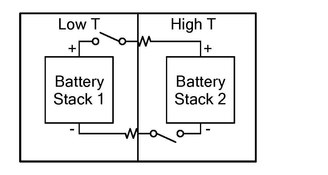
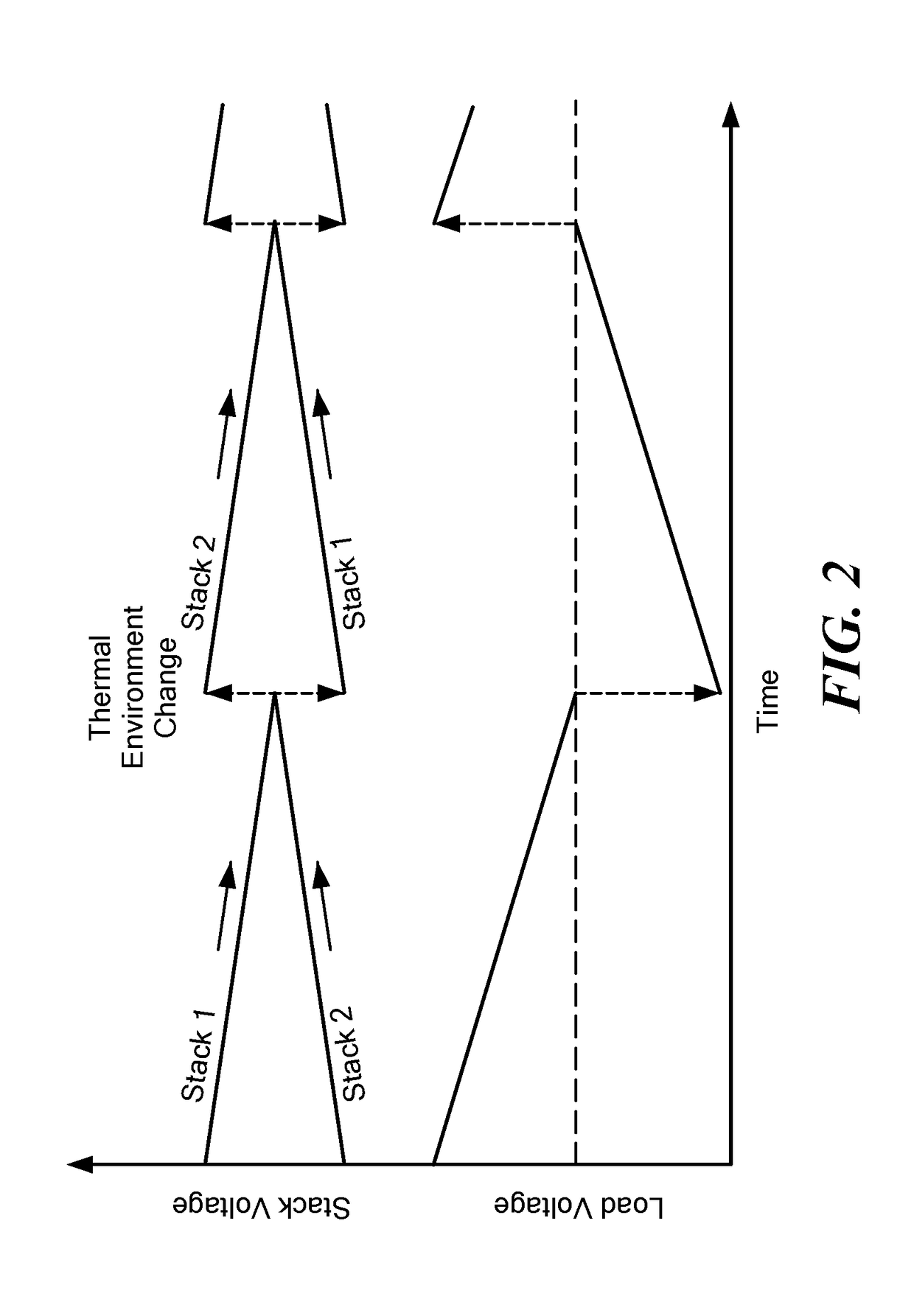
[0024]Resistance values for the electrical load can be chosen to match the desired power output per period. In a first experimental example with a LiCoO2 (LCO) Dual Cell system, load resistances of 100 Ω and 1000 Ω were chosen to determine the trend of power and resistance for the circuit. The battery sources were placed in 10° C. and 40° C. thermal environments, and the cells were swapped in open circuit configuration. Ten minutes were allowed after switching the cells to allow thermal equilibrium.

[0025]Current value was determined using Ohm's law and direct measurement of the drop in potential across the load resistor. FIG. 4A shows a graph of adjusted potential (V) for two thermal cycles in a 2 cell LCO circuit with 100 Ω load resistor, and FIG. 4B shows the same thing for a 2 cell LCO circuit with 1000 Ω load resistor. The orange values at the top of those graphs correspond to positive terminals, and the purple values correspond to the negative terminals. A...

example 2

LiV2O5 (LVO) Dual Cell

[0028]A second experimental example used a LiV2O5 (LVO) Dual Cell system where The cells were LixV2O5 / Li—Al (LVO) commercial cells (Panasonic VL2020). Like the LCO system, resistance values for the circuit can be chosen to match the desired power output per period. Resistances of 100 Ω and 1000 Ω were chosen to determine the trend of power and resistance for the circuit. Cells were placed in 10° C. and 40° C. temperature thermal environments, and the cells were swapped in open circuit configuration. Ten minutes were allowed after switching the cells to allow thermal equilibrium.

[0029]FIG. 5A shows a graph of adjusted potential (V) over time where the red numbers correspond to estimation of the state of charge when comparing OCV values to GITT measurements of the cell, and black numbers correspond to calculated changes to the state of charge from the calculated current changes. These number correspond well, indicating the change in voltage represents a change in...

example 3

Single Temperature Charge-Free System

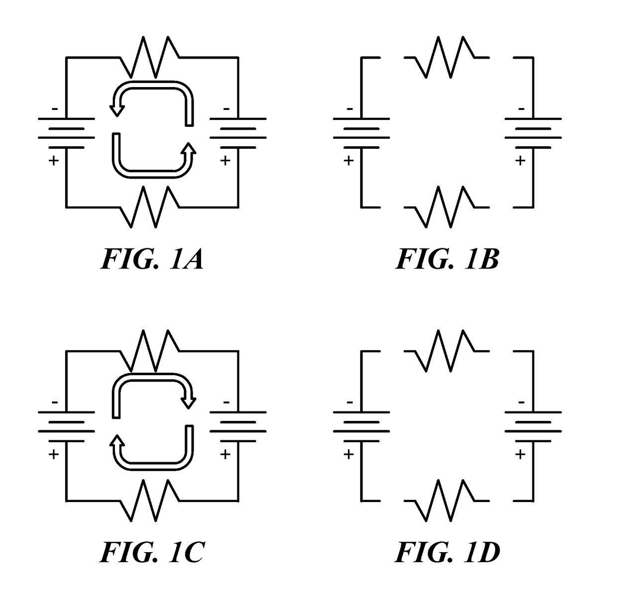
[0032]A third experimental example used a single common thermal environment for both battery sources. The single temperature system, unlike the dual temperature system, cannot use two of any cell. Instead, the cells need to be of equal open circuit voltage, while the cell should possess different temperature coefficients. The larger the difference in the temperature coefficients, the better, and ideally they would have different signs. If the cells begin at an average temperature at the same voltage, then closing the circuit would result in no current. Increasing the temperature of the cells creates a net potential. If the circuit is closed, then a current can be observed. Cooling the cells to a cold temperature then creates a new potential. Closing the circuit then drives current in the other direction. Both of these actions are spontaneous (i.e. do not require external charging).

[0033]A 7-cell system was constructed by wiring stacks of homemade...


PUM

PropertyMeasurementUnit
temperatureaaaaaaaaaa
electrical potentialaaaaaaaaaa
temperaturesaaaaaaaaaa

Abstract

A thermogalvanic electrochemical system includes two battery sources connected together in a switchable circuit to provide electric current to an electrical load in the circuit. The battery sources are located in a thermal environment having a varying temperature, and each battery source has a corresponding electrical potential that varies with temperature of the thermal environment. A power management processor operates the circuit to: form a closed circuit at a first temperature with current flow from a first battery source through the electrical load to a second battery source until reaching a first thermal equilibrium, and then form an open circuit, then form a closed circuit at a second temperature with current flow from the second battery source through the electrical load to the first current source until reaching a second thermal equilibrium, and then form an open circuit.

Description

[0001]This application claims priority from U.S. Provisional Patent Application 62 / 503,001, filed May 8, 2017, which is incorporated herein by reference in its entirety.TECHNICAL FIELD[0002]The present invention relates to electrochemical systems that use thermogalvanic effect to convert heat differences into electrical work.BACKGROUND ART[0003]Currently, traditional primary and secondary batteries are the primary sources of power for wireless sensors such as those that are used in the internet of things and other industrial and agricultural applications. These sensors, however, require charging or replacing the batteries with frequencies that range from daily to bi / tri-monthly for some ultra-low power sensors. In order to decrease the frequency of changing batteries, system capabilities are often compromised in order to operate at ultra-low power.[0004]It also is known that electrochemical cells can vary their electrochemical equilibrium with temperature, a property referred to as ...

Claims


Application Information

Patent Timeline
Patent Type & Authority Applications(United States)
IPC IPC(8): H01M10/44H01M10/42H01M10/0525
CPCH01M10/441H01M10/425H01M10/0525H01M10/443H01M2010/4271H01G9/21Y02E60/10
Inventor XU, LINLINFORD, PATRICK ALANTHOMPSON, II, CARL VERNETTESHAO-HORN, YANG
Owner MASSACHUSETTS INST OF TECH
Why Eureka
Try Eureka