
Lighting device

Inactive Publication Date: 2018-11-01
FUJIFILM CORP
View PDF4 Cites 0 Cited by
  • Summary
  • Abstract
  • Description
  • Claims
  • Application Information

AI Technical Summary

Benefits of technology

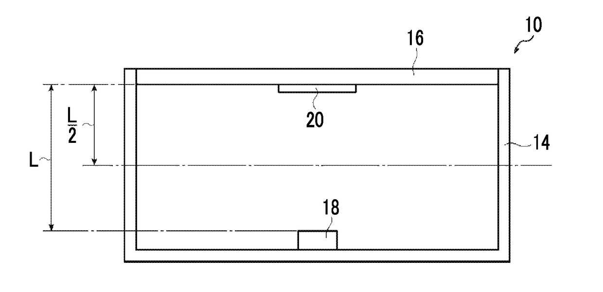
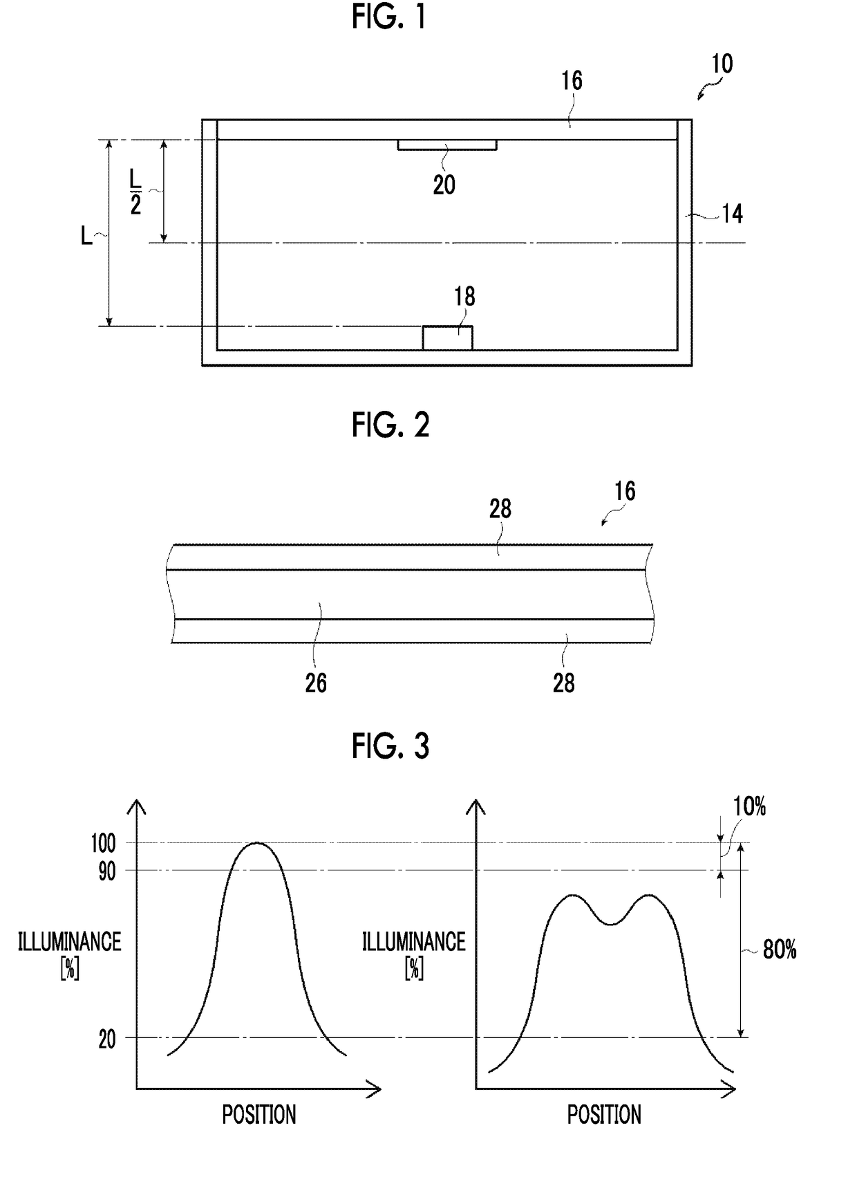
The present invention provides a lighting device that prevents deterioration of a wavelength conversion layer due to light and heat from a light source, has high durability, and has a long lifespan. This is achieved by using a light intensity reduction member that reduces peak illuminance of light that is applied by the point light source on a light incident surface of the wavelength conversion member by 10% to 80%, and absorbance of light having a wavelength of 450 nm measured by using an integrating sphere is less than 5%. This results in reduced heat and light damage to the wavelength conversion member, leading to increased durability and lifespan of the lighting device.

Problems solved by technology

However, the wavelength conversion member is easily damaged by light or heat in many cases, and the wavelength conversion member is deteriorated with the lapse of time due to heat and light from the light source.
Particularly, in a case where an LED or the like is used as a light source, the light source generates much heat, has high illuminance of light, and thus the wavelength conversion member is significantly deteriorated.
Therefore, the lighting device using a wavelength conversion member in the related art has a problem in that light having an intended intensity of light may not be applied to the entire surface in the plane direction due to the use for a long period of time.

Method used


Image

  • Lighting device
  • Lighting device
  • Lighting device

Examples


example 1

[0262]28>

[0263]As the supporting substrate, a PET film (COSMOSHINE A4300 manufactured by Toyobo Co., Ltd., thickness 50 μm) was prepared. A barrier layer was formed on one side of the supporting substrate by the following procedure.

[0264]A barrier layer was formed on one side of the supporting substrate by the following procedure.

[0265]Trimethylolpropane triacrylate (manufactured by Daicel-Cytec Co., Ltd.) and a photopolymerization initiator (ESACURE KT046 manufactured by Lamberti S.p.A.) were prepared and weighed so as to have the mass ratio of 95:5, and these were dissolved in methyl ethyl ketone, so as to obtain a coating solution having a concentration of solid contents of 15%.

[0266]This coating solution was applied to a supporting substrate by roller-to-roller by using a die coater and was caused to pass through a drying zone at 50° C. for three minutes. Thereafter, the coating solution was irradiated with ultraviolet rays in a nitrogen atmosphere (integrating accumulate irradi...

example 2

[0302]The lighting device 10 was manufactured in the same manner as in Example 1 except for changing the light intensity reduction member 20 to a white PET film and using a reflection film having a thickness of 65 μm (ESR manufactured by The 3M Company).

[0303]The integrated absorbance and the peak illuminance reduction rate were measured in the same manner as in Example 1. As a result, the integrated absorbance was 2%, and the peak illuminance reduction rate was 45%.

example 3

[0304]18 g of polymethyl methacrylate (DIANAL BR-85 manufactured by Mitsubishi Rayon Co., Ltd., weight-average molecular weight of 200,000 g / mol) was introduced to a mixed solution of 70 g of methylene chloride and 10.4 g of methanol and stirred for one hour so as to be dissolved.

[0305]2 g of titanium oxide (CR-97 manufactured by Ishihara Kogyo Co., Ltd.) having a particle diameter of 0.25 μm was introduced to the mixed solution in which the polymethyl methacrylate resin was dissolved and was further stirred for one hour, so as to obtain a coating solution.

[0306]The lighting device 10 was manufactured in the same manner as in Example 1 except for suctioning 0.4 ml of this coating solution with a micropipette, dropwise adding the coating solution in the central part of the wavelength conversion sheet 16, and drying the coating solution at 70° C. for 10 minutes, so as to obtain the light intensity reduction member 20. The light intensity reduction member 20 had a thickness of 12 μm an...


PUM


Abstract

There is provided a lighting device using a wavelength conversion sheet used in a liquid crystal display or the like, and an object of the invention is to provide a lighting device having satisfactory durability. The object is achieved by a lighting device including: a point light source; a wavelength conversion sheet; and a light intensity reduction member arranged between the point light source and the wavelength conversion layer, in which the light intensity reduction member reduces peak illuminance of light that is applied by the point light source on a light incident surface of a wavelength conversion sheet by 10% to 80%, and absorbance of light having a wavelength of 450 nm measured by using an integrating sphere is less than 5%.

Description

CROSS-REFERENCE TO RELATED APPLICATIONS[0001]This application is a Continuation of PCT International Application No. PCT / JP2016 / 087770 filed on Dec. 19, 2016, which claims priority under 35 U.S.C. § 119(a) to Japanese Patent Application No. 2015-250683 filed on Dec. 22, 2015 and Japanese Patent Application No. 2016-016095 filed on Jan. 29, 2016. Each of the above applications is hereby expressly incorporated by reference, in its entirety, into the present application.BACKGROUND OF THE INVENTION1. Field of the Invention[0002]The present invention relates to a lighting device used for a backlight or the like of a liquid crystal display device.2. Description of the Related Art[0003]A liquid crystal display device (hereinafter, referred to as an LCD) expands applications thereof as an image display device that has low power consumption and saves spaces. In the recent liquid crystal display device, as the improvement in LCD performance, further power saving, the improvement in color repr...

Claims


Application Information

Patent Timeline
IPC IPC(8): G02F1/1347G02F1/1335H01L33/50F21V9/40
CPCG02F1/13473G02F1/133611G02F1/133603H01L33/505G02F2001/1351G02F1/133606H01L33/44H01L33/507G02F1/133614G02F1/1351
Inventor TOYAMA, HIROFUMISATAKE, RYOYONEMOTO, TAKASHIOBA, TATSUYACHIKUSHI, NATSURU
Owner FUJIFILM CORP
Learn More