
Method of performing surface measurements on a surface of a sample, and scanning probe microscopy system therefore

Active Publication Date: 2018-10-25
NEDERLANDSE ORG VOOR TOEGEPAST-NATUURWETENSCHAPPELIJK ONDERZOEK (TNO)
View PDF1 Cites 3 Cited by
  • Summary
  • Abstract
  • Description
  • Claims
  • Application Information

AI Technical Summary

Benefits of technology

The present invention provides a method for accurately estimating the force between a probe tip and a sample surface during contact moments. This is achieved by capturing two or more frequency components from the sensor signal, which provides more information regarding tip-sample interactions. The method uses a recursive filter to efficiently apply the digital signal processing method for providing accurate force estimates. The estimation is computationally inexpensive, easily real-time implemented, robust, and captures all statistically relevant information. The estimated force consistently approaches the real amount of tip-sample interactions.

Problems solved by technology

In general, it is important to keep the forces constant during the scanning, however it is not possible to measure these forces with the methods applied.
However, since these forces occur only during a short fraction of a tapping cycle, the cantilever only responds to the periodic average of the forces.
Since only the average of the forces affect the cantilever, and countless different types of forces can have the same average, it is impossible to fully estimate the forces from TM-AFM signals.

Method used


Image

  • Method of performing surface measurements on a surface of a sample, and scanning probe microscopy system therefore
  • Method of performing surface measurements on a surface of a sample, and scanning probe microscopy system therefore
  • Method of performing surface measurements on a surface of a sample, and scanning probe microscopy system therefore

Examples


Embodiment Construction

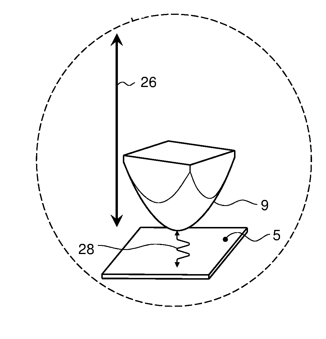
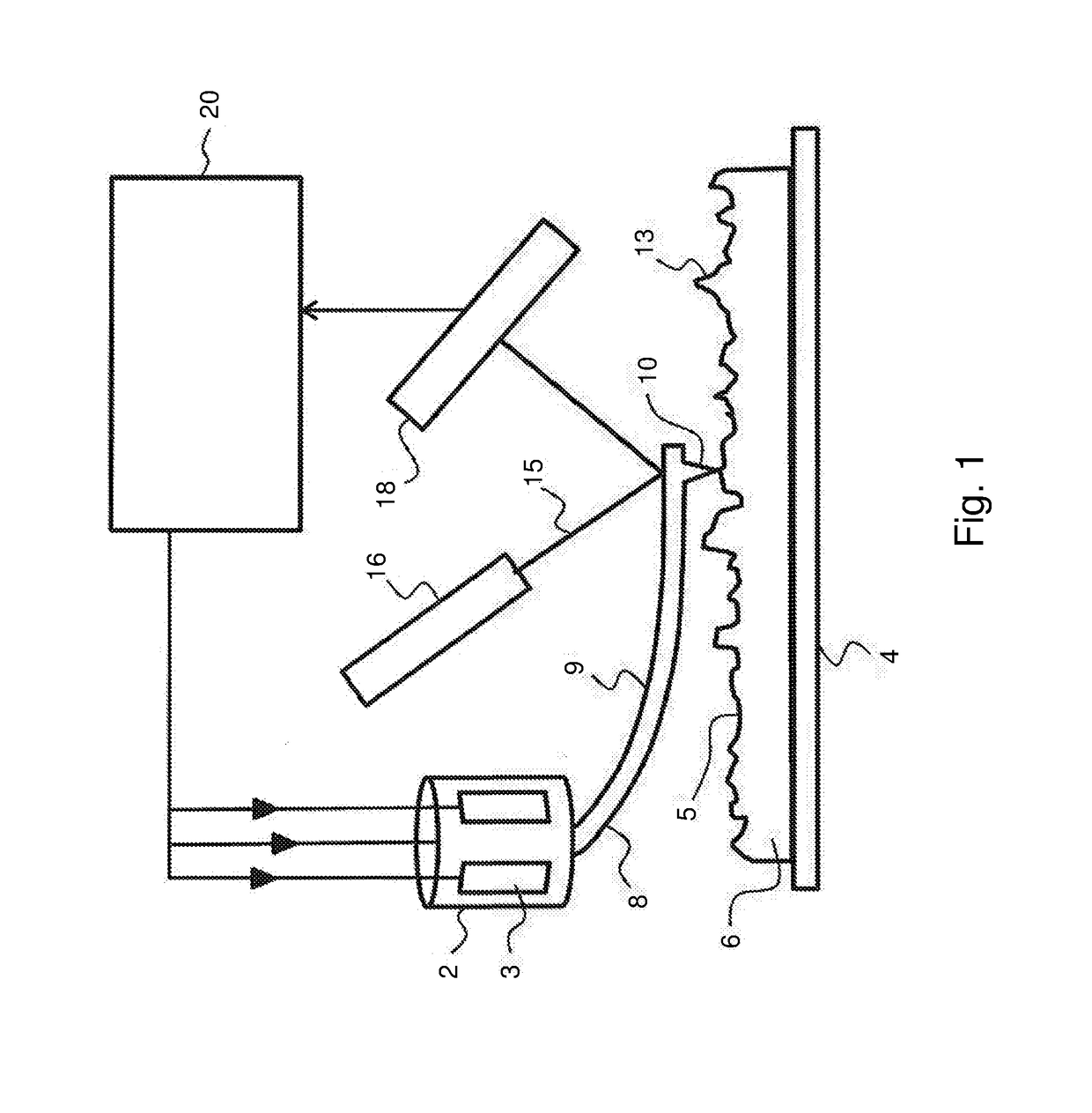
[0039]FIG. 1 schematically illustrates the working principle of a typical prior art atomic force microscope. In FIG. 1, a probe head 2 comprises piezo type drivers 3 for the X-, Y-, and Z-directional motion of a probe 8. The probe 8 consists of a cantilever 9 having a probe tip 10 arranged for scanning a sample surface 5 of a sample 6. During scanning, a dither piezo (not shown) or other means of actuations such as photo-thermal actuation, electrostatic, etc, may drive the cantilever in vibrational mode (for example close to resonant frequency) to enable tapping of the probe tip on the surface. The manner of applying a vibrational motion to the probe tip is known to the skilled person.

[0040]Scanning of the sample surface 5 is performed by moving the probe tip 10 in the X- and Y direction parallel to the sample surface 5 (or alternatively, by moving the substrate surface in the X- and Y-directions while maintaining the position of the probe tip fixed in the X- and Y-directions). The ...


PUM


Abstract

This document relates to a method of performing surface measurements on a surface of a sample using a scanning probe microscopy system. The system comprises a sample support structure for supporting a sample, a sensor head including a probe comprising a cantilever and a probe tip arranged on the cantilever, and an actuator for scanning the probe tip relative to the substrate surface for mapping of the nanostructures. The method comprising the steps of: vibrating the cantilever using an actuator and moving the probe relative to the substrate surface for performing said scanning. The probe is held at a distance to the substrate surface such as to allow contact at a plurality of intermittent contact moments between the probe tip and the surface during said vibrating of the cantilever. The steps of vibrating of the cantilever and moving of the probe are performed concurrently. For performing the surface measurements, the method comprises obtaining a sensor signal indicative of a position of the probe tip during said scanning, and analyzing this signal by quantifying two or more frequency components in a Fourier transform for determining an estimate of a force value of a force between said substrate surface and said probe tip during said contact moments.

Description

FIELD OF THE INVENTION[0001]The present invention is directed at a method of performing surface measurements on a surface of a sample using a scanning probe microscopy system, the system comprising a sample support structure for supporting a sample, a sensor head including a probe comprising a cantilever and a probe tip arranged on the cantilever, and an actuator for scanning the probe tip relative to the substrate surface for mapping of the nanostructures, the method comprising the steps of: vibrating the cantilever using an actuator; moving the probe relative to the substrate surface for performing said scanning, wherein said probe is held at a distance to the substrate surface such as to allow contact at a plurality of intermittent contact moments between the probe tip and the surface during said vibrating of the cantilever; wherein the steps of vibrating of the cantilever and moving of the probe are performed concurrently. The invention is further directed at a scanning probe mi...

Claims


Application Information

Patent Timeline
IPC IPC(8): G01Q20/00G01Q30/04G01Q60/32
CPCG01Q20/00G01Q30/04G01Q60/32G01Q60/34
Inventor SADEGHIAN MARNANI, HAMEDKEYVANI JANBAHAN, ALIASGHAR
Owner NEDERLANDSE ORG VOOR TOEGEPAST-NATUURWETENSCHAPPELIJK ONDERZOEK (TNO)
Learn More