Amusement device with tilting rotatable structure

a technology of rotating structure and amusement device, which is applied in the direction of amusement device, great wheel, russian swing, etc., can solve the problems of not so much pleasing, expensive and not so much effective, and the cost of equipment and its implementation

Active Publication Date: 2018-10-25
ANTONIO ZAMPERLA SPA
View PDF0 Cites 0 Cited by
  • Summary
  • Abstract
  • Description
  • Claims
  • Application Information

AI Technical Summary

Benefits of technology

The present invention simplifies and streamlines the design of an amusement device, reducing its size and allowing for more attractions in the park. The device has a four-bar linkage structure that allows for easy and accurate control of the relative rotation among its parts. This arrangement also provides efficient load distribution and allows for easy adjustment of its relative position. This makes it easier for vehicles to move close to the ground, improving user experience. Overall, the invention provides a more compact, flexible, and cost-effective amusement device.

Problems solved by technology

A problem for these amusement devices are costs of the equipment and its implementation, the latter needing works to house the base the arm is constrained to.
Furthermore, the presence of an arm protruding from the structure is not so much pleasing to the eye and usually needs additional camouflage works, which are on the other hand expensive and not so much effective.
Moreover, as the arm moving the rotating structure is, in the load position, contained in the bulk of the rotating structure itself, housing structures for the base to which the arm is constrained are not necessarily implemented.

Method used


Image

  • Amusement device with tilting rotatable structure
  • Amusement device with tilting rotatable structure
  • Amusement device with tilting rotatable structure

Examples


Embodiment Construction

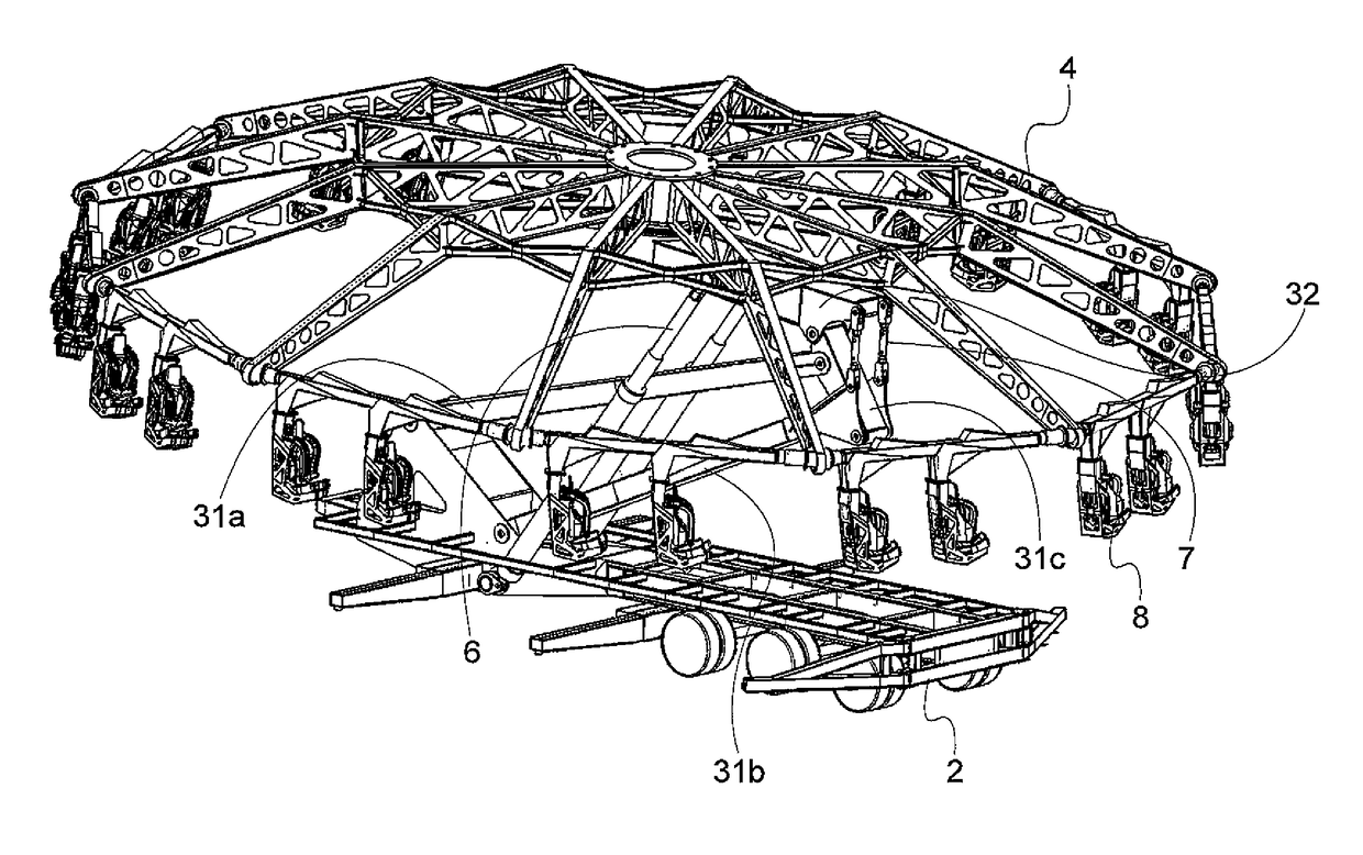
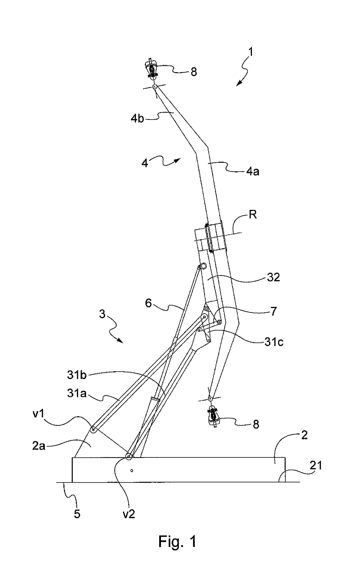
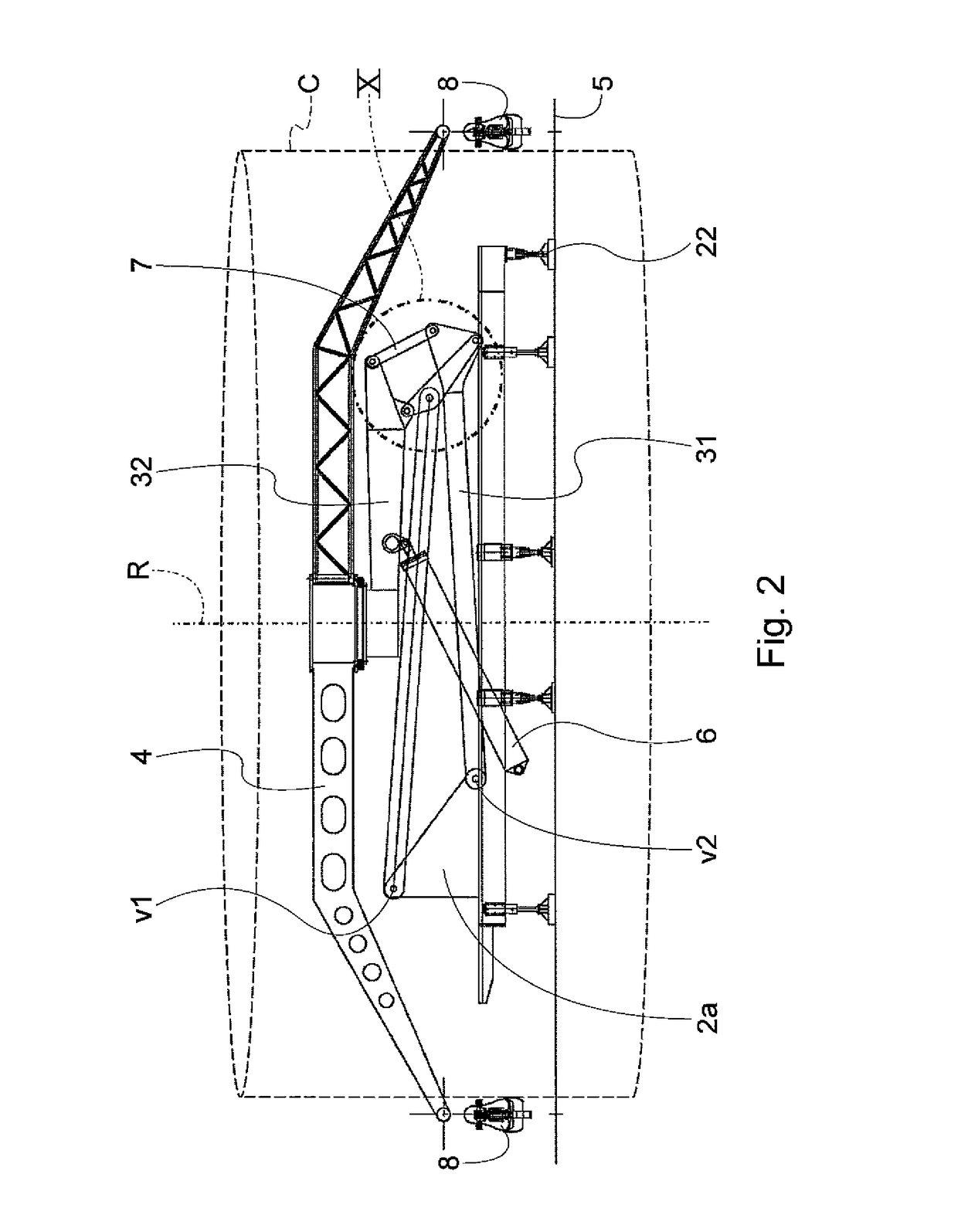
[0034]Referring to the attached figures, an amusement device 1 according to the present invention comprises a base structure 2, an arm 3 and a rotating structure 4.

[0035]The arm 3 has two or more mutually movable portions 31, 32.

[0036]The rotating structure 4 is provided with one or more vehicles 8 for one or more passengers. The rotating structure 4 is further rotatably constrained to the arm 3 around a rotation axis R.

[0037]Movement means 6 are constrained to the arm 3 and thereby move the rotating structure 4 between at least one passenger load position (shown in FIG. 6), and a second rotation position of the structure (shown in FIG. 8).

[0038]Preferably, in the load position, the rotation axis R is substantially perpendicular to the ground 5, or anyway to the surface on which the base structure 2 rests.

[0039]Furthermore, in the load position, preferably passengers can get in all vehicles 8 of the amusement device 1. In other words, in the load position, all vehicles 8 of the amus...


PUM


Abstract

Amusement device comprising a base structure (2), an arm (3) constrained at least rotationally to said base structure (2), a rotating structure (4) provided with at least one vehicle (8) and rotatably constrained, with respect to one end of said arm, around a rotation axis (R), and movement means (6) for moving the arm between at least a first load position in which passengers are loaded, and a second rotation position of the rotating structure (4). The arm comprises at least two portions (31, 32) mutually movable, and in the load position, the arm portions are completely comprised in a cylinder (C) having an axis that is said rotation axis (R), and having a radius that is the distance from the vehicle to the rotation axis.

Description

FIELD OF THE INVENTION[0001]The present invention concerns an amusement device with a tiltable rotating structure. More particularly, the invention concerns an amusement device of the type in which an arm has a rotating structure provided with a plurality of passenger vehicles.PRIOR ART[0002]A number of amusement devices of this type are known in the art. Amusement devices known as “ferris wheel” have one or more fixed arms bearing the wheels with vehicles, in general gondolas that can house more than one passenger. In these amusement devices, passengers enter and go out of vehicles when the wheel move the latter next to a load / unload position, usually in the lowest part of the wheel. Because passengers use this entry / going out method, the rotation speed of the amusement device and the passenger payload per hour are necessarily reduced.[0003]To solve this problem amusement devices have been suggested, in which the rotating structure is mounted on an arm acting also as a lifter to be...

Claims


Application Information

Patent Timeline
IPC IPC(8): A63G27/04A63G1/44A63G27/02A63G1/28
CPCA63G27/04A63G1/44A63G27/02A63G1/28A63G2200/00
Inventor SORIANI, CLAUDIO
Owner ANTONIO ZAMPERLA SPA
Why Eureka
Try Eureka