
Driving force control system for vehicle

a technology for controlling system and driving force, which is applied in the direction of electric control, machines/engines, transportation and packaging, etc., can solve the problems of sudden start, stepwise change of driving force, failure to increase driving force, etc., and achieve the effect of improving acceleration feeling

Active Publication Date: 2018-10-18
TOYOTA JIDOSHA KK
View PDF0 Cites 7 Cited by
  • Summary
  • Abstract
  • Description
  • Claims
  • Application Information

AI Technical Summary

Benefits of technology

The patent describes a control system for vehicles that adjusts the output of the engine based on the input of the driver through the accelerator. This technology ensures that the vehicle accelerates smoothly and comfortably, improving the driver's experience. The control system reduces the rate of acceleration when the vehicle is being driven at a certain speed, allowing for a more pleasant and comfortable driving experience.

Problems solved by technology

Thus, the control on the torque of the engine performed while the vehicle is downshifted results in the driving force changing stepwise.
A torque output according to the position of the accelerator pedal at this point might result in sudden start.
Unfortunately, this configuration might result in a failure to increase the driving force according to an acceleration demand, issued with the accelerator pedal further depressed, when torque response delay or the like occurs due to a change in an operation status of the engine.
However, the system cannot reduce or eliminate a period during which the driving force plateaus due to the torque response delay described above and the like.
Thus, the system also involves a risk that the driving force does not reflect the accelerating operation.
The system further involves a risk that the driving force temporarily plateaus or changes stepwise due to speed change operation, resulting in a failure to achieve the driving force reflecting the accelerating operation by the driver.

Method used


Image

  • Driving force control system for vehicle
  • Driving force control system for vehicle
  • Driving force control system for vehicle

Examples


Embodiment Construction

)

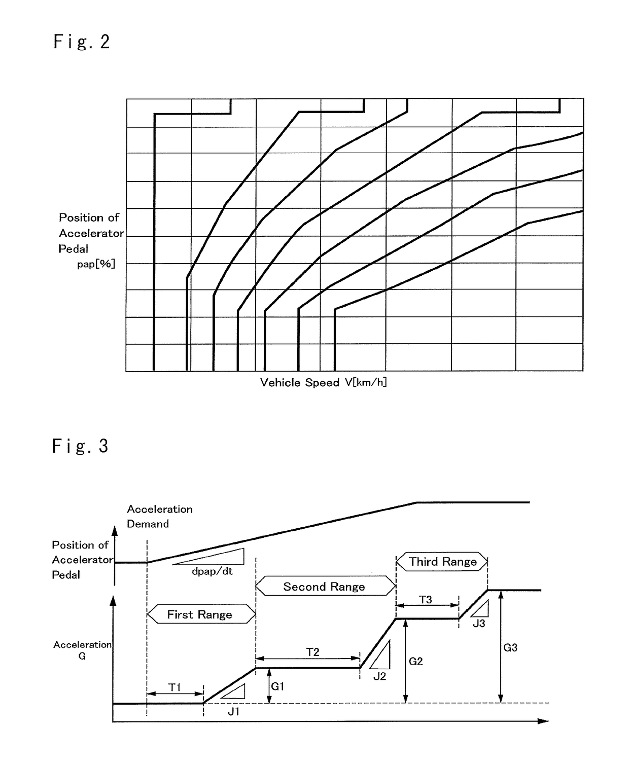
[0029]FIG. 1 shows an example of a vehicle Ve having a drive unit D according to an embodiment of the disclosure. The drive unit D comprises an engine (referred to as “ENG” in FIG. 1) 1 as a prime mover and an automatic transmission (referred to as “AT” in FIG. 1) 7. For example, a gasoline engine and a diesel engine may be employed as the engine 1, and the engine 1 is provided with an electronic throttle valve 2 to control an air intake of the engine 1 and an air flow meter 3 to detect the air intake. According to the example shown in FIG. 1, the engine 1 is further provided with a supercharger Ta that is activated to supply compressed air to the engine 1 when a torque greater than a predetermined magnitude is demanded.

[0030]The electronic throttle valve 2 is adapted to control air supply to the engine 1 on the basis of a command signal transmitted from an after-mentioned electronic control unit (to be abbreviated as the “ECU” hereinafter) 12. Specifically, the electronic throttle...


PUM


Abstract

A driving force control system for a vehicle configured to control a driving force based on the accelerating operation by the driver. The vehicle comprises a drive unit including a prime mover and a transmission, an accelerator device; and a controller. The controller is configured to: calculate an operating amount of the accelerator device; calculate an operating speed of the accelerator device; calculate a target jerk; and control an output torque of the drive unit based on the target jerk, when the operating amount is smaller than a predetermined amount, and the operating speed is slower than a predetermined speed.

Description

CROSS REFERENCE TO RELATED APPLICATION[0001]The present application claims the benefit of Japanese Patent Application No. 2017-082319 filed on Apr. 18, 2017 with the Japanese Patent Office.BACKGROUNDField of the Disclosure[0002]Embodiments of the present disclosure relate to a system for controlling a driving force of a vehicle according to an acceleration demand from a driver.Discussion of the Related Art[0003]JP-A-2009-121238 discloses a driving force control system for a vehicle including an engine and a geared automatic transmission. The driving force control system is configured to control a torque of the engine according to the position of the accelerator pedal during a normal operation. A gear stage of the automatic transmission is switched on the basis of the position of the accelerator pedal and a vehicle speed. Thus, the control on the torque of the engine performed while the vehicle is downshifted results in the driving force changing stepwise. In this context, the drivin...

Claims


Application Information

Patent Timeline
Patent Type & Authority Applications(United States)
IPC IPC(8): B60W30/19B60W10/06B60W10/10F02D41/00
CPCB60W30/19B60W10/06B60W10/10F02D41/0007B60W2540/10B60W2720/106F02D2200/1002F02D2200/602B60W10/11B60W40/00B60W2710/1005B60W2710/0666F02D41/0225F02D41/045F02D41/10F02D2200/501B60W2520/10B60W2540/106Y02T10/12
Inventor KITAGAWA, HIROYASU
Owner TOYOTA JIDOSHA KK
Learn More