
High-stability step gauge and preparation method therefor

a step gauge and high-stability technology, applied in the field of step gauges, can solve the problems of not being able to adapt to the needs of non-contact measurement technology development, affecting the accuracy and stability of step gauges, and large volume of existing step gauges, etc., to achieve the effect of good accuracy and stability, small volume and strong function

Active Publication Date: 2018-09-13
GAN TAIXI
View PDF0 Cites 0 Cited by
  • Summary
  • Abstract
  • Description
  • Claims
  • Application Information

AI Technical Summary

Benefits of technology

The present invention provides a high-stability step gauge with good accuracy and stability, a small size, and strong functions. The base body and gauge block mounting blocks are designed to reduce deformation errors caused by factors such as weight. The gauge pieces are distributed in a straight line on the base body, and accuracy and stability of mounting and positioning are high. The combination of gauge blocks and standard balls can expand the applicable scope of the step gauge and provide check demands of multiple coordinate measuring devices with multiple specifications. The method for preparing a high-stability step gauge is simple and efficient and has low costs. The sleeved gauge block mounting blocks have high fixed mounting stability, and positioning and assembly of the gauge pieces are accurate.

Problems solved by technology

Therefore, to ensure accuracy, an existing step gauge is relatively heavy and has a relatively large volume and high manufacturing costs.
In addition, because of limitation of a structure of the base body, a manufacturing process is relatively complex and cannot adapt to needs of development of a non-contact measurement technology.
Secondly, precise gauge blocks are commonly used as measurement surface generation bodies and are hardly applicable to a non-contact measurement device such as a photographing-type measurement device.

Method used


Image

  • High-stability step gauge and preparation method therefor
  • High-stability step gauge and preparation method therefor
  • High-stability step gauge and preparation method therefor

Examples


Embodiment Construction

[0035]The present disclosure will now be described more fully hereinafter with reference to the accompanying drawings, in which exemplary embodiments of the invention are shown. This invention may, however, be embodied in many different forms and should not be construed as limited to the embodiments set forth herein. Rather, these embodiments are provided so that this disclosure will be thorough and complete, and will fully convey the scope of the invention to those skilled in the art. Like reference numerals refer to like elements throughout.

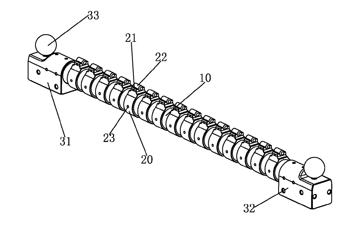
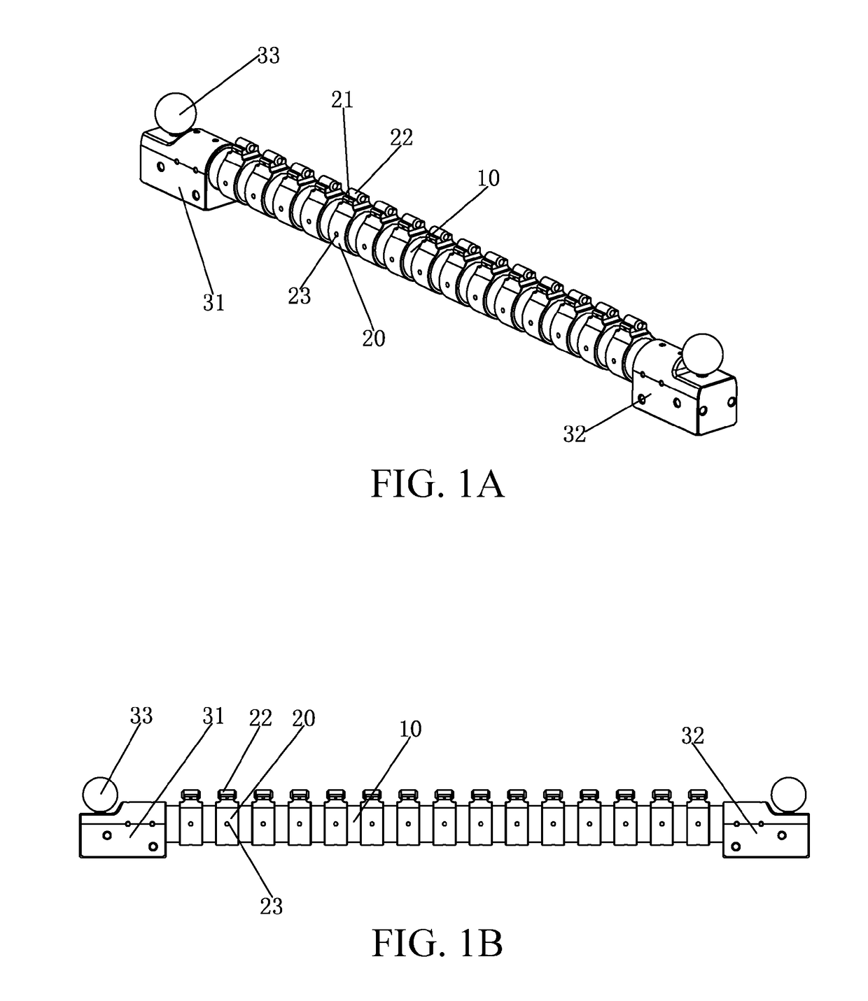
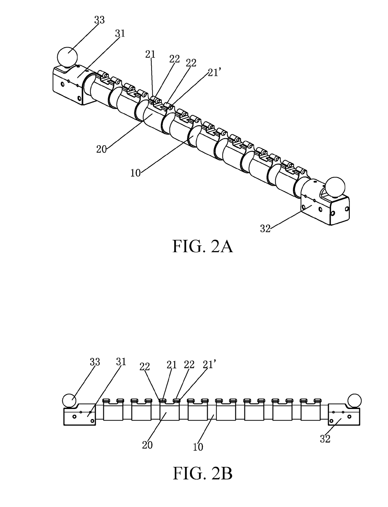
[0036]The high-stability step gauge mainly implements functional focusing of a base body and gauge block mounting blocks of a whole step gauge by using a pillar carrier disposed along a coordinate direction as the base body and distributing the gauge block mounting blocks on the pillar carrier, improving whole stability.

[0037]In the high-stability step gauge shown in FIG. 1A and FIG. 1B, the base body thereof is a pillar carrier disposed along ...


PUM


Abstract

A high-stability step gauge and a preparation method therefor, where the step gauge has a base body, the base body includes a pillar carrier disposed along a coordinate direction, gauge block mounting blocks are distributed on the pillar carrier, and gauge pieces are fixedly mounted on the gauge block mounting blocks. The high-stability step gauge has good accuracy and stability, a small size, and strong functions. Deformation errors caused by the step gauge due to factors such as a weight of the base body are effectively and prominently reduced by means of reasonable combination of the base body and the gauge block mounting blocks. The preparation method thereof provides a stable length direction low deformation performance by using a cylindrical rigid support as the base body. The sleeved gauge block mounting blocks have high fixed mounting stability, and positioning and assembly of the gauge pieces are accurate.

Description

CROSS-REFERENCE TO RELATED PATENT APPLICATION[0001]This application claims priority to and the benefit of, pursuant to 35 U.S.C. § 119(a), patent application Serial No. CN201710130389.5 filed in China on Mar. 7, 2017. The disclosure of the above application is incorporated herein in its entirety by reference.[0002]Some references, which may include patents, patent applications and various publications, are cited and discussed in the description of this disclosure. The citation and / or discussion of such references is provided merely to clarify the description of the present disclosure and is not an admission that any such reference is “prior art” to the disclosure described herein. All references cited and discussed in this specification are incorporated herein by reference in their entireties and to the same extent as if each reference were individually incorporated by reference.FIELD[0003]The present invention relates to a step gauge for calibration of moving accuracy of a machine ...

Claims


Application Information

Patent Timeline
Patent Type & Authority Applications(United States)
IPC IPC(8): G01B21/04G01B3/30G01B5/008G01B5/00
CPCG01B21/047G01B3/303G01B5/008G01B5/0004G01B5/0011G01B21/042
Inventor GAN, TAIXI
Owner GAN TAIXI
Learn More