A vibration damping connector and use of the vibration damping connector

a technology of vibration damping connector and connector, which is applied in the direction of mechanical equipment, instruments, optical elements, etc., can solve the problems of mechanical vibration and/or noise in the system or the optical imaging system, reducing the quality of the image and subsequently the data to be extracted

Active Publication Date: 2018-08-16
INL INT IBERIAN NANOTECHNOLOGY LAB
View PDF1 Cites 6 Cited by
  • Summary
  • Abstract
  • Description
  • Claims
  • Application Information

AI Technical Summary

Benefits of technology

[0023]According to at least one exemplary embodiment said first shock absorbing element is arranged to said second part by using adhesive. By attaching the at least one first shock abs

Problems solved by technology

Sometimes the system or the optical imaging system is exposed to mechanical vibrations and/or noise, for example from the system

Method used


Image

  • A vibration damping connector and use of the vibration damping connector
  • A vibration damping connector and use of the vibration damping connector
  • A vibration damping connector and use of the vibration damping connector

Examples


Embodiment Construction

[0035]An embodiment of the invention will be described in more detail in the following with reference to the accompanying drawings.

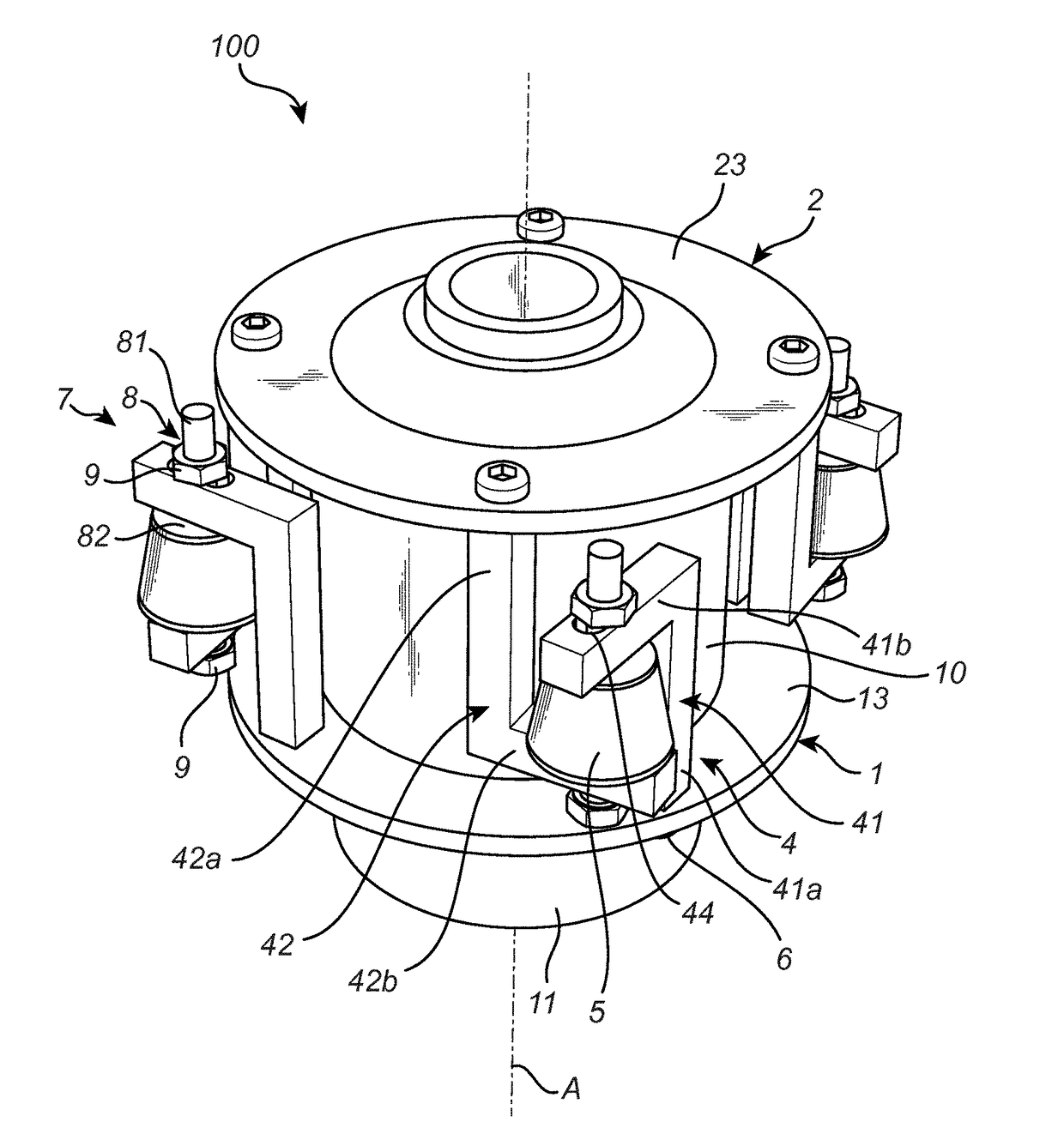
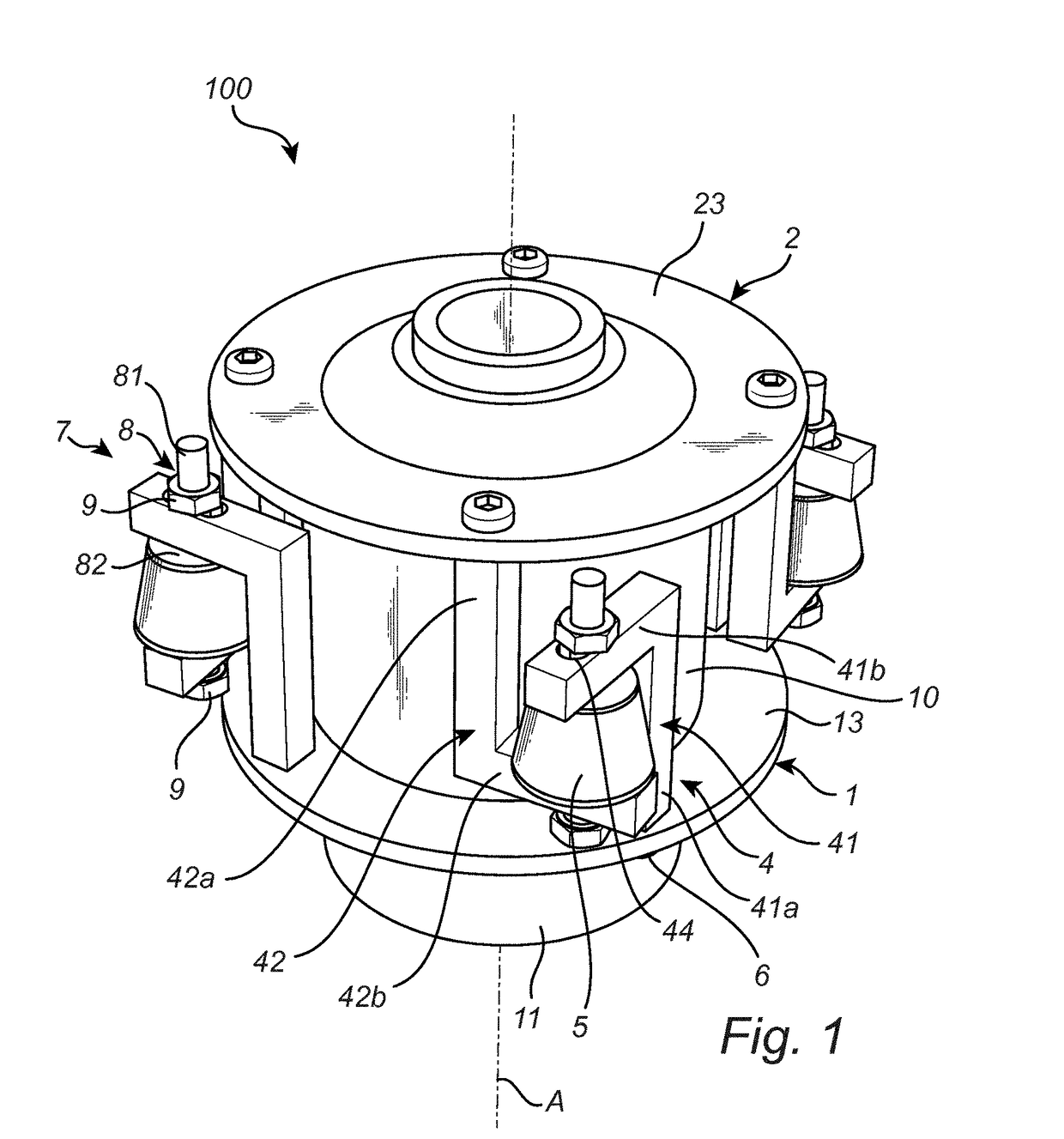
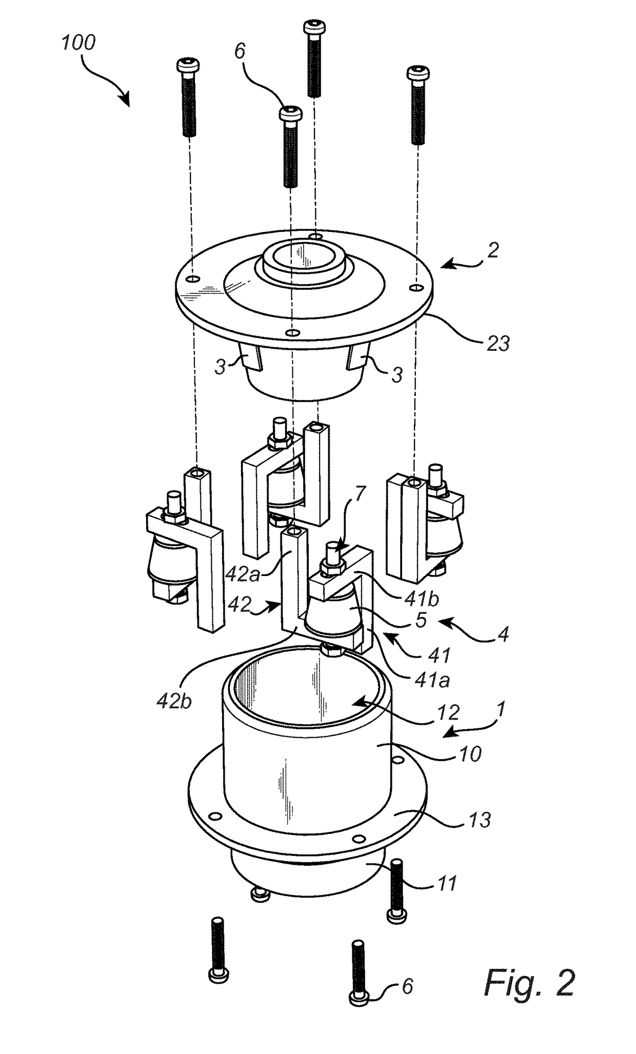
[0036]FIGS. 1, 2 and 3 show a vibration damping connector 100, which can take up vibration and / or noise between two systems. The FIGS. 1, 2 and 3 will be described together. The vibration damping connector 100 may for example take up vibration and / or noise between a vibration prone system, for example a differential spinning disk, and / or an optical Imaging system, for example an microscope.

[0037]The vibration damping connector 100 comprises a first part 1 and a second part 2, where the second part 2 is inserted into the first part 1 along a common central axis A. The first part 1 is a female part 1 and the second part 2 is a male part 2.

[0038]The first part 1 comprises a main portion 10 and an end portion 11. The main portion 10 comprises an outer cylindrical shape with a through hole 12 (see FIG. 3) having a first portion 14, a second portion 15 and a t...


PUM


Abstract

The present invention refers to a vibration damping connector (100) for reducing vibrations between a vibration prone system and an optical imaging system, said vibration damping connector comprising a first part (1) adapted to be connected to said optical imaging system, a second part (2) adapted to be connected to said vibration prone system, and at least one first shock absorbing element (3), a portion of said first part (1) is arranged inside a portion of said second part (2) along a central axis (A) or a portion of said second part (2) is arranged inside a portion of said first part (1) along a central axis (A) and said at least one flexible shock absorbing element (3) is arranged between said first part (1) and said second part (2), said vibration damping connector (100) further comprises at least one fastening device (4) for fastening said first part (1) to said second part (2) and said fastening device (2) presses said first part(1) to said second part (2) via a second shock absorbing element (5). Furthermore, use of the vibration damping. connector, in an optical system is disclosed.

Description

FIELD OF THE INVENTION[0001]The present invention relates to a vibration damping connector for reducing vibrations between a vibration prone system and an optical imaging system. Furthermore, use of the vibration damping connector in an optical system is disclosed.TECHNICAL BACKGROUND[0002]Within optics and optical instruments it is common to use a connector, also known as a C-mount. The connector may attach a vibration prone system, for example an Atomic Force Microscope (AFM), with a charge-coupled device (CCD) digital camera system with a cooling fan or an optical imaging system with motorized components such as e.g. a spinning disk. The connector is usually according to a known standard for optical imaging sensors that dictates the design of the mount shape and sensor distance with respect to the optical mount in optical imaging. At the time of filing the present application the connectors are according to the ISO 10935:2009. Sometimes the system or the optical imaging system is...

Claims


Application Information

Patent Timeline
IPC IPC(8): G02B27/64F16F15/08
CPCG02B27/646F16F15/08F16F2226/042F16F2230/0005F16F2234/04G01Q30/025G02B7/14G02B21/0088G02B21/362
Inventor DE BEULE, PIETERMIRANDA, ADELAIDEMARTINS, MARCO
Owner INL INT IBERIAN NANOTECHNOLOGY LAB
Why Eureka
Try Eureka