Multiple input touch dimmer lighting control

Active Publication Date: 2018-08-09
BRIGHTGREEN
View PDF4 Cites 43 Cited by
  • Summary
  • Abstract
  • Description
  • Claims
  • Application Information

AI Technical Summary

Benefits of technology

The patent text describes a method for controlling a touch panel device in a home automation system. The device detects movement and can light up the touch surface when an object is close to it, making it easier to find and operate in the dark. The method also analyzes data from sensors, device logs, or additional input to predict when to perform an operation and improve accuracy. Additionally, the method can analyze data to suggest ways to reduce energy consumption.

Problems solved by technology

Prior art touch dimmers have tended to duplicate the controls provided by a conventional mechanical switch and rotary dimmer.

Method used


Image

  • Multiple input touch dimmer lighting control
  • Multiple input touch dimmer lighting control
  • Multiple input touch dimmer lighting control

Examples


first embodiment

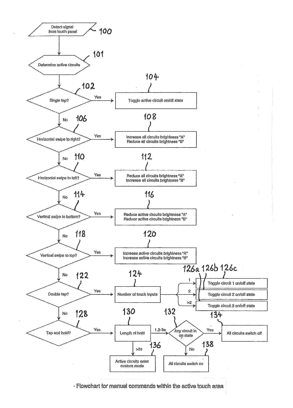
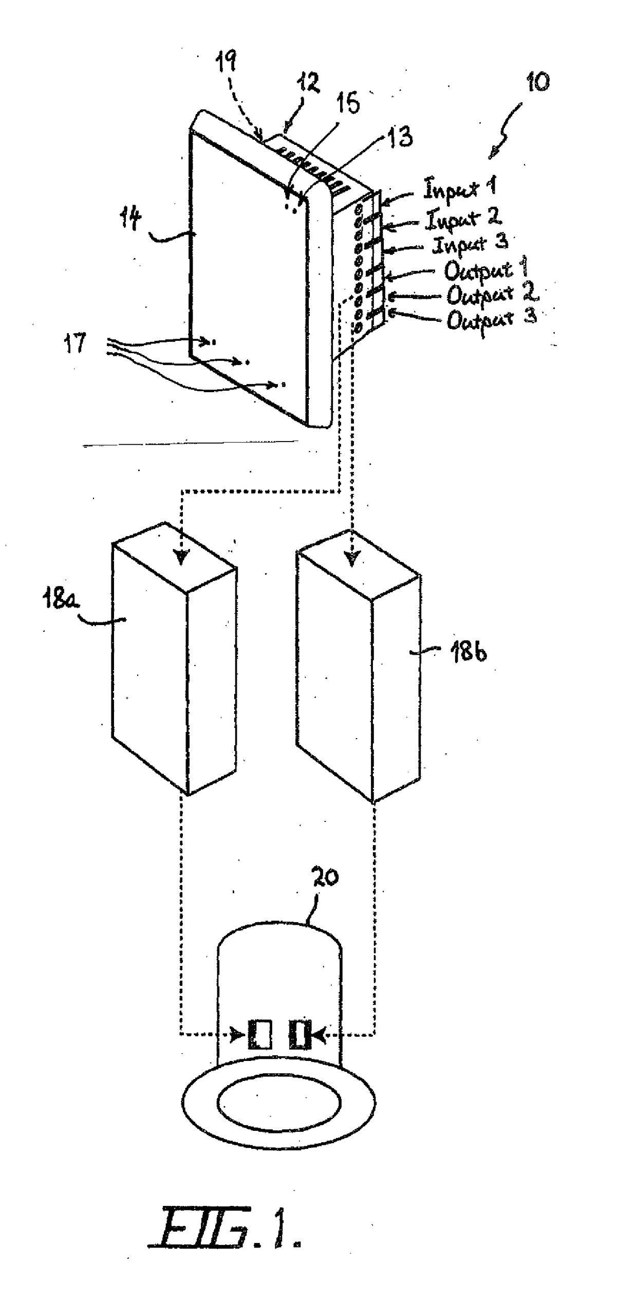
[0046]a touch dimmer lighting control system 10 in accordance with the invention, as illustrated in FIGS. 1 to 4, comprises a touch panel device 12 having a touch sensitive surface 14. The touch sensitive surface 14 is capable of detecting movement of a touch input in first and second directions. The touch input detected is typically that provided by a human finger, but may also be a touch input provided by another object. The control system 10 also includes a processing means 16 for generating control signals based on this detection. The processing means 16 is typically a programmable electronic device, such as a PLC or EEPROM, which controls the logic of the control signals generated according to a preset control program. FIGS. 5 to 9 illustrate in flow chart form a typical control program and control routines employed in the processing means 16 for generating the control signals, based on the detected movement of a touch input on the touch sensitive surface 14 and other inputs. T...

second embodiment

[0081]Further variations to the invention are envisaged including variations as to the action of touching the touch panel of the touch panel device so as to produce differing lighting effects. FIG. 10 is a flowchart for a typical control algorithm employed in a processing means for a touch panel device in a touch dimmer lighting control system in accordance with the invention. After a touch input is sensed at step 32 the type of touch input is determined at step 34. The touch panel device and the touch sensitive surface of this embodiment are similar in design to that of the touch panel device 12 and the touch sensitive surface 14. Additional settings may be provided which are activated from the touch panel by providing different types of touch input to the touch sensitive surface. If it is detected at step 34 that the touch input is a “Small” touch, for example, by touching the touch sensitive surface with a light touch, the processing means first detects the power state of the tou...


PUM


Abstract

The invention relates to a touch panel device for a dimmer lighting control system, the device comprising a touch sensitive surface capable of detecting a touch input; a light sensor that detects ambient light levels within a sensing area adjacent to the device; a processing means operatively connected to the touch sensitive surface and the light sensor for generating control signals based on detection of the touch input on the touch sensitive surface and / or ambient light levels wherein, in use, the total light output of a light circuit can be controlled manually with the touch panel device and / or controlled autonomously by the level of ambient light in the sensing area.

Description

FIELD OF THE INVENTION[0001]The present invention relates to a multiple input lighting control system and method and relates particularly to a touch dimmer lighting control system and method which is able to determine and control the desired light levels of an area in response to one or more factors.PATENT OF ADDITION[0002]This application is for an improvement or modification to the invention disclosed in co-pending Australian patent application No 2012325685 filed on 12 Oct. 2012.BACKGROUND TO THE INVENTION[0003]Touch dimmer lighting control systems are known in the art which employ a touch panel to vary the brightness of a single light circuit. The touch panel replaces a conventional light switch and rotary dimmer control knob. For example, US Patent Application No 2010 / 0301682 by Huang, filed 2 Dec. 2010, describes a feather-touch dimming switch which comprises an enclosure having a mounting surface, a flat plate button mounted on the mounting surface, a dimming button, a trippi...

Claims


Application Information

Patent Timeline
IPC IPC(8): H05B37/02G05B11/01
CPCH05B37/0227G05B11/01H05B37/0218H05B37/0272G05B15/02G06F3/04883G06F3/03547G08B13/19619G08B13/19695G05B2219/13031G05B2219/2613G05B2219/2642G05B2219/2664H05B47/11H05B47/13H05B47/19H05B47/125Y02B20/40G06F3/0488H03K17/96
Inventor O'DRISCOLL, DAVIDNATHAN, MOFFATCARTER, TRENT
Owner BRIGHTGREEN
Why Eureka
Try Eureka