
Packaging machine having moisture sensor

a technology of moisture sensor and packaging machine, which is applied in the direction of program control, instruments, applications, etc., can solve the problems of reducing the performance of the packaging machine, requiring a high degree of experience, and only being able to carry out the approach, so as to reduce the cost of personnel and increase the clock performance

Active Publication Date: 2018-08-09
MULTIVAC SEPP HAGGENMULLER GMBH & CO KG
View PDF5 Cites 6 Cited by
  • Summary
  • Abstract
  • Description
  • Claims
  • Application Information

AI Technical Summary

Benefits of technology

The invention is a sealing station that uses a moisture sensor in an evacuation line to detect moisture in a production process. This helps to improve the production of the sealing tool lower part. The process of starting the sealing station depends on the detected process values in the production process and in other work units running simultaneously. This prevents delays and reduces clock cycle times. When multiple processes are involved, the target process value in the next process is only started when a predetermined time interval is between them. Overall, this invention improves the efficiency and accuracy of the sealing process.

Problems solved by technology

However, during adjusting the process times of the packaging machine, time delays often occur due to which the performance of the packaging machine is considerably reduced.
This cautious approaching requires a high degree of experience and may only be carried out by skilled personnel.
Thereby, it is a problem that detecting the absolute moisture value does not constitute a suitable measured variable for all products to justify an abort of the evacuation operation.
Rather, there are also products in which the signal detected at the moisture sensor varies, since the effective moisture value fluctuates so that an abort of the evacuating operation is not always justified.
In addition, the absolute moisture value does not constitute a suitable measured variable in order to determine a tendency of the pressure distribution within the packaging based on which it could be determined whether the desired vacuum pressure in the package interior may be generated or not in spite of the presence of moisture.

Method used


Image

  • Packaging machine having moisture sensor
  • Packaging machine having moisture sensor
  • Packaging machine having moisture sensor

Examples


Embodiment Construction

[0093]The invention will now be described with reference to the drawing figures, in which like reference numerals refer to like parts throughout. For purposes of clarity in illustrating the characteristics of the present invention, proportional relationships of the elements have not necessarily been maintained in the drawing figures.

[0094]The following detailed description of the invention references specific embodiments in which the invention can be practiced. The embodiments are intended to describe aspects of the invention in sufficient detail to enable those skilled in the art to practice the invention. Other embodiments can be utilized and changes can be made without departing from the scope of the present invention. The present invention is defined by the appended claims and the description is, therefore, not to be taken in a limiting sense and shall not limit the scope of equivalents to which such claims are entitled.

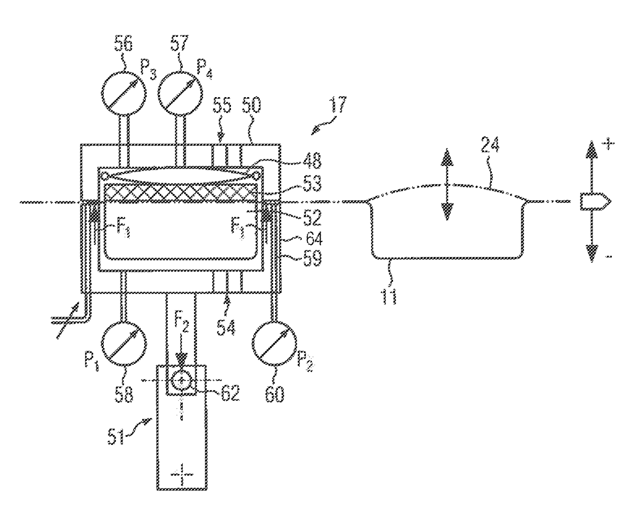
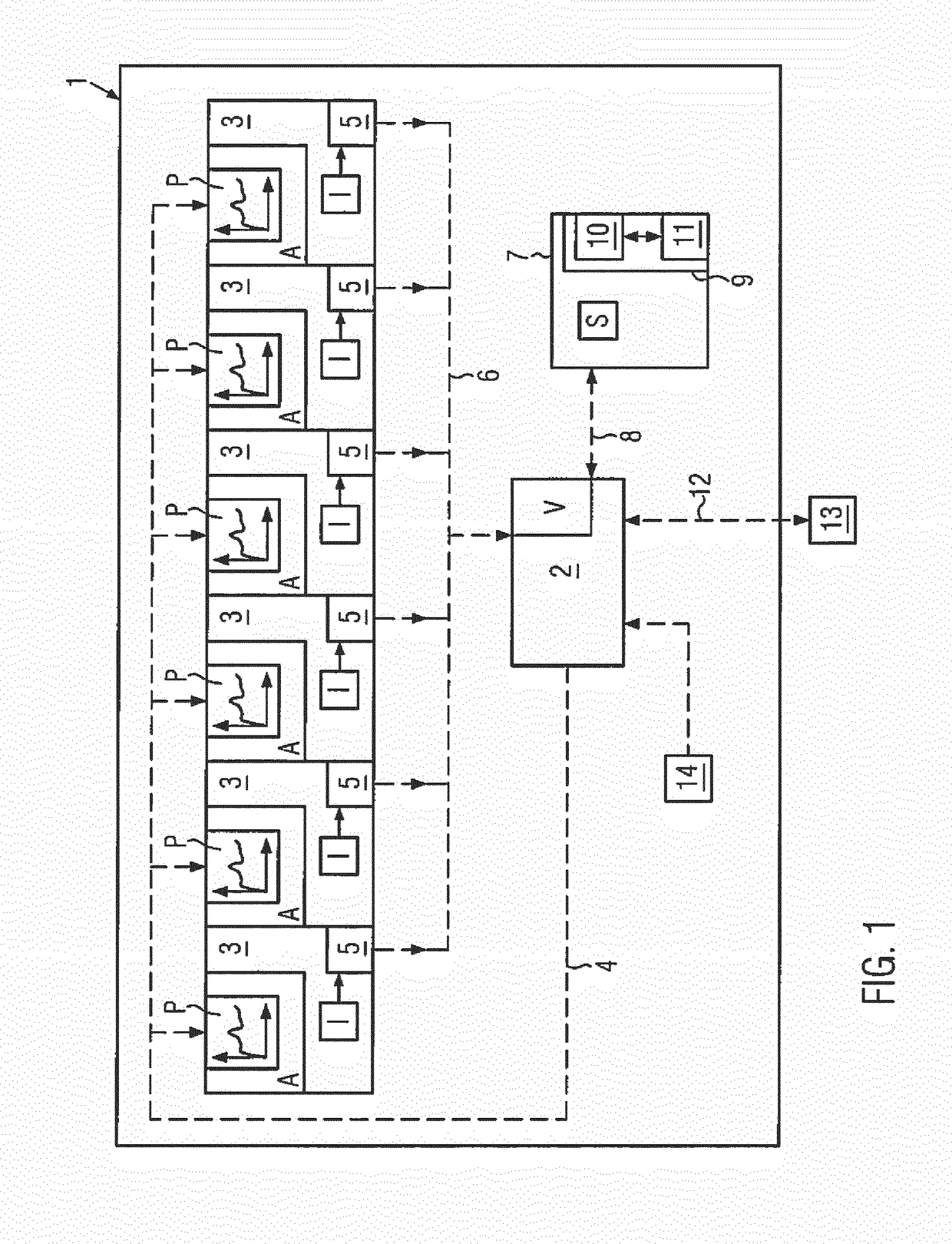
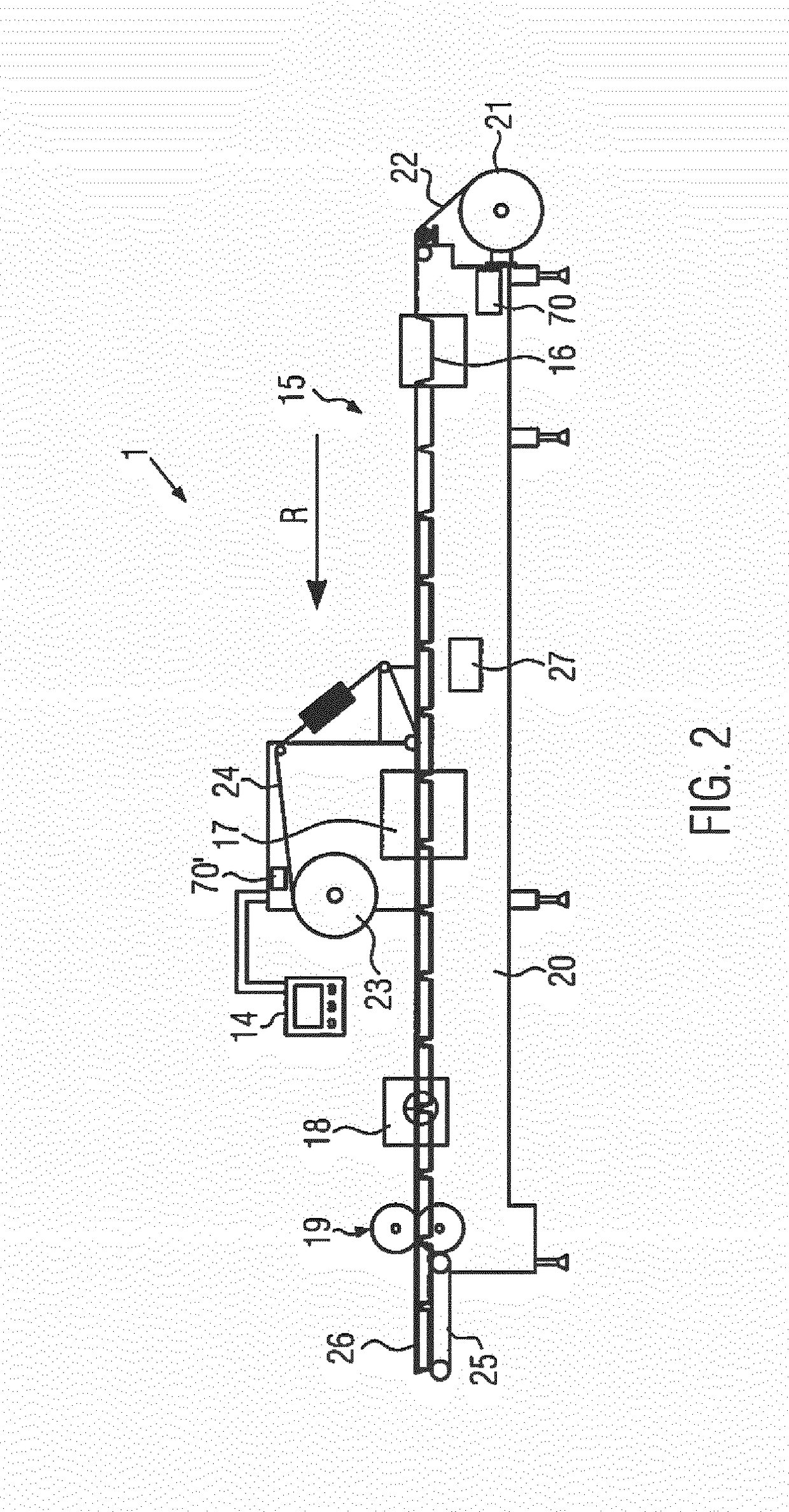
[0095]FIG. 1 shows in a schematic view a packaging machine ...


PUM

PropertyMeasurementUnit
timeaaaaaaaaaa
timeaaaaaaaaaa
vacuum pressureaaaaaaaaaa

Abstract

A packaging machine, comprising a control unit, at least one measurement device and a plurality of work units for different processes. One of the work units is designed as a sealing station which comprises at least one moisture sensor designed as the measurement device which is functionally connected to the control unit and is designed to detect moisture within the sealing station as a time-dependent measured variable during a program sequence of the sealing station. The program sequence may comprise an evacuation process, wherein the control unit is designed to calculate a rate of change in the moisture during the evacuation process of the sealing station. The control unit may abort the evacuation process performed on the sealing station, based on the rate of change, before reaching a target vacuum pressure within the sealing station, immediately or after a specified delay time elapses.

Description

FIELD OF THE INVENTION[0001]The present invention relates to a self-controlling packaging machine and a method of using a self-controlling packaging machine.BACKGROUND OF THE INVENTION[0002]In known packaging machines, the production process consists of a plurality of individual processes, for example, closing chamber, heating, molding, evacuating, gassing, sealing, opening chamber, and safety times in order to sufficiently ventilate or aerate chambers.[0003]Thereby, the individual processes are time-controlled, wherein the individual processes run successively, where appropriate, temporarily overlapping or separately by safety time intervals. The respective process times in particular depend on a chamber volume, film types, motion sequences, and switching times of valves of the packaging machine and therefore, have to be preset in a complex manner by the machine operators for each machine equipment as well as for each product to be manufactured at the operating console of the packa...

Claims


Application Information

Patent Timeline
Patent Type & Authority Applications(United States)
IPC IPC(8): B65B57/00B65B9/04B65B47/02B65B51/10B65B31/02B29C51/46B29C65/18B29C65/00G05B19/042
CPCB65B31/022B29C51/46B29C65/18B29C66/00145B29C66/53461B29C66/82421B29C66/83221B29C66/9121B29C66/849B29C66/9141B29C66/9221B29C66/92443B29C66/92921B29C66/953G05B19/0426G05B2219/23012B65B9/04B65B47/02B65B57/00B65B51/10B65B51/14B65B2051/105G05B2219/45048B29C66/112B29C66/131B29C66/81455B29C66/9231B29C66/924B29C66/944B29L2031/712
Inventor EHRMANN, ELMARBOTZENHARDT, CLAUSHOLDERIED, THOMASFELCH, FLORIANENDERLE, TOBIAS
Owner MULTIVAC SEPP HAGGENMULLER GMBH & CO KG
Learn More