Drive unit for vehicles

Active Publication Date: 2018-07-26
TOYOTA JIDOSHA KK
View PDF8 Cites 4 Cited by
  • Summary
  • Abstract
  • Description
  • Claims
  • Application Information

AI Technical Summary

Benefits of technology

The patent is about a drive unit for vehicles that helps increase the speed of a motor or generator used as a prime mover, while preventing the temperature from rising and causing damage. The technical effect of this invention is to improve the performance and efficiency of vehicle drives while protecting against heat-related issues.

Problems solved by technology

However, if the motor is thus rotated while causing a slip in the engagement device, the engagement device would be damaged by the friction heat.
Such damage on the engagement device may be limited by reducing friction of the engagement device.
However, if the friction of the engagement device is reduced, a rotational speed of the motor cannot be raised to avoid the single phase lock.
Otherwise, the engagement device is almost released and hence a drive torque cannot be transmitted sufficiently to propel the vehicle.
However, Japanese Patent Laid-Open No. 2011-231857 does not disclose a possibility of the single phase lock and a means to avoid the single phase lock.

Method used


Image

  • Drive unit for vehicles
  • Drive unit for vehicles
  • Drive unit for vehicles

Examples


Embodiment Construction

)

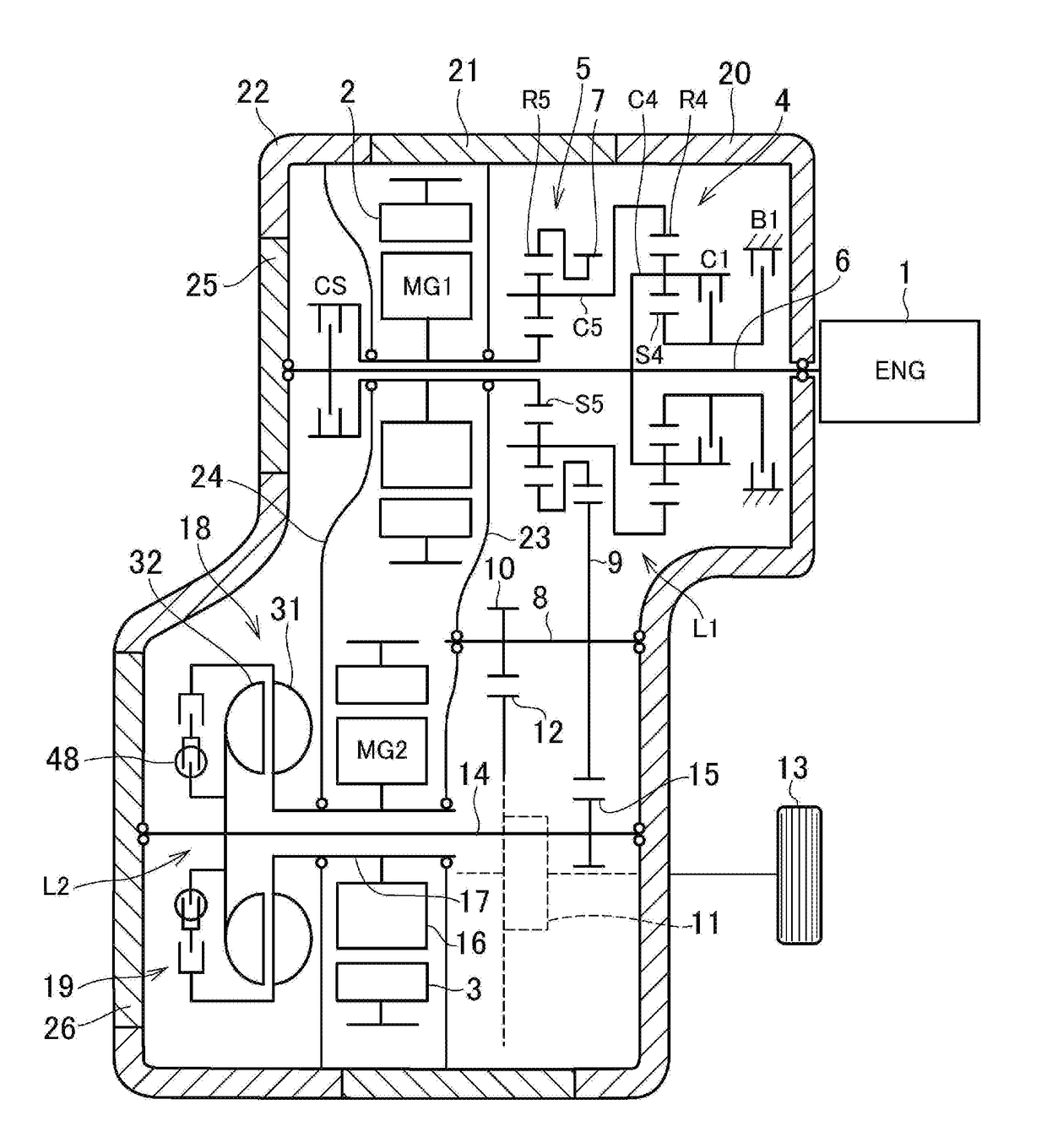
[0033]FIG. 1 is a skeleton diagram showing one embodiment of a two-motor type hybrid drive unit to which the present disclosure is applied. A prime mover includes an engine 1 and two motors 2, 3. The first motor 2 serves as a rotating electrical machine of the embodiment, and the second motor 3 serves as another rotating electrical machine of the embodiment. An internal combustion engine such as a gasoline engine and a diesel engine may be employed as the engine 1 (ENG), and a permanent magnet type three-phase synchronous motor such as a motor-generator (MG1, MG2) may be employed as each of the motors 2 and 3.

[0034]An overdrive mechanism 4, a power split mechanism 5, and the first motor-generator (MG1) 2 are arranged in order coaxially with the engine 1. In order to increase a speed of the engine 1, a single-pinion planetary gear set is used as the overdrive mechanism 4. Specifically, the overdrive mechanism 4 includes a sun gear S4, a ring gear R4 arranged coaxially with the sun g...


PUM


Abstract

A vehicle drive unit to prevent a single phase lock of a motor as a prime mover to limit damage is provided. The drive unit includes: a first transmission route to deliver drive force of an engine to drive wheels; and a second transmission route to deliver drive force of a motor to the drive wheels. The second transmission route comprises an intermediate shaft that transmits the drive force of the motor to the first transmission route. A fluid coupling is disposed between the motor and the intermediate shaft. A lockup clutch is arranged parallel to the fluid coupling between the motor and the intermediate shaft.

Description

TECHNICAL FIELD[0001]This invention relates to the art of a drive unit for a vehicle in which a prime mover includes at least one motor.BACKGROUND ART[0002]Japanese Patent Laid-Open No. 2006-256560 describes a power output unit in which a motor as a prime mover is connected to a transmission, and in which a torque is delivered to a right derive wheel and a left drive wheel through a differential gear. If the motor generates a large drive force when stopping or when rotated at a low speed, one of coils of specific phase would be heated by overcurrent. Such phenomenon is called a “single phase lock”. In order to avoid the single phase lock, according to the teachings of Japanese Patent Laid-Open No. 2006-256560, an engagement device such as a brake of a transmission is controlled in such a manner as to cause a slip, and the motor is controlled in such a manner as to generate a target drive torque.[0003]Japanese Patent Laid-Open No. 2011-231857 describes a driving device having a motor...

Claims


Application Information

Patent Timeline
IPC IPC(8): B60K6/445B60K6/365B60K6/48B60K28/16B60L3/00B60W10/08B60W10/02B60L50/16
CPCB60K6/445B60K6/365B60K6/48B60K28/165B60L3/003B60W10/08B60W10/023B60Y2200/92F16H2045/0252B60L2240/36B60K6/26B60K6/38B60K6/405B60W10/026B60W30/1843B60W2510/087B60W2710/024B60Y2400/426B60W20/50Y02T10/62Y02T10/72Y02T10/70Y02T10/7072
Inventor IMAMURA, TATSUYATABATA, ATSUSHIOKUDA, KOICHIIMAI, KEITA
Owner TOYOTA JIDOSHA KK
Why Eureka
Try Eureka