
Common phase error (CPE) compensation for frequency division multiplex (FDM) symbols in wireless communication systems

a frequency division multiplex and frequency division technology, applied in multiplex communication, orthogonal multiplex, baseband system details, etc., can solve the problems of high overhead, leakage degrade the orthogonality of the ofdm waveform,

Active Publication Date: 2018-07-12
NATIONAL INSTRUMENTS
View PDF3 Cites 19 Cited by
  • Summary
  • Abstract
  • Description
  • Claims
  • Application Information

AI Technical Summary

Benefits of technology

The present invention provides a wireless base station or user equipment that compensates for a common phase error (CPE) in a received frequency division multiplexed (FDM) symbol. This is achieved by pre-processing the FDM symbol to obtain its constituent equalized FDM data subcarriers, and then using a CPE estimator to extract a subset of the equalized FDM data subcarriers from each region of a constellation diagram associated with the modulation scheme used by the transmitter to generate the FDM data subcarriers. An overall CPE estimate is then computed by averaging the region-specific CPE estimates. The wireless base station or user equipment compensates each of the equalized FDM data subcarriers using the overall CPE estimate. The invention also provides a method for compensating CPE in each of a series of FDM symbols received by a wireless receiver. The technical effect of the invention is to improve the quality of wireless communication by compensating for CPE in the received FDM symbols.

Problems solved by technology

The phase noise at each subcarrier frequency also introduces ICI to the neighboring subcarriers, and this spectral leakage degrades the orthogonality of the OFDM waveform.
This CPE estimation based on a static pilot pattern, therefore, has the drawback of high overhead due to required pilot signaling for the purely pilot aided PN compensation.

Method used


Image

  • Common phase error (CPE) compensation for frequency division multiplex (FDM) symbols in wireless communication systems
  • Common phase error (CPE) compensation for frequency division multiplex (FDM) symbols in wireless communication systems
  • Common phase error (CPE) compensation for frequency division multiplex (FDM) symbols in wireless communication systems

Examples


Embodiment Construction

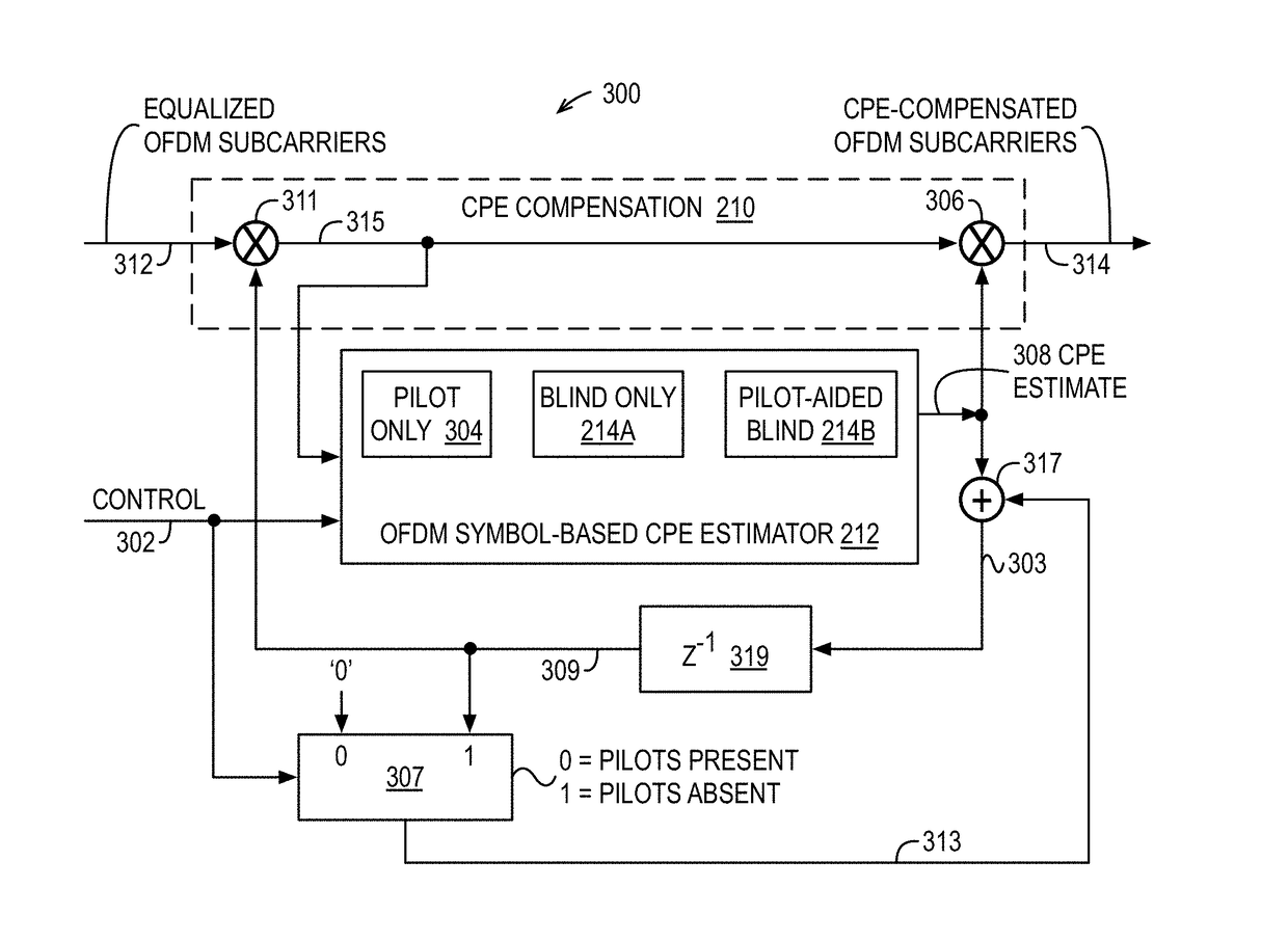
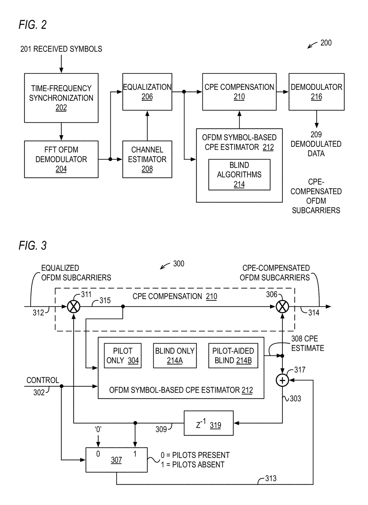
[0028]The disclosed embodiments provide efficient techniques for common phase error (CPE) compensation for OFDM (orthogonal frequency division multiplexing) symbols in wireless communications using blind algorithms that may reduce pilot overhead while keeping the CPE compensation performance close to a pilot-only approach. The disclosed embodiments in part utilize blind phase noise estimation algorithms for CPE compensation, and disclosed blind CPE compensation techniques can be used in a variety of deployment scenarios including eMBB (enhanced Mobile BroadBand), URLLC (ultra-reliable low latency communications), mMTC (massive machine type communications), and / or other use cases. The proposed blind CPE estimation algorithms do not suffer from the overhead of pilot-only CPE compensation. The disclosed methods and related systems are directed to FDM (frequency division multiplexing) modulation schemes where the full symbol is received before PN is estimated and compensated. Examples o...


PUM


Abstract

A wireless device receives a frequency division multiplexed (FDM) symbol of constituent equalized FDM data subcarriers. A modulation scheme constellation diagram is subdivided into two or more regions. For each of the regions, a subset of the subcarriers that fall within the region are extracted and a respective region-specific CPE estimate is computed thereon. The respective region-specific CPE estimates are averaged to produce an overall CPE estimate used to compensate the subcarriers. Furthermore, a first CPE estimate is computed using pilot symbols embedded in a first received FDM symbol and is used to compensate the subcarriers. A following second FDM symbol that has no embedded pilot symbols is compensated using the first CPE estimate, and a second CPE estimate is computed using a blind estimation method on the second FDM symbol compensated subcarriers, which are compensated using the second CPE estimate.

Description

CROSS REFERENCE TO RELATED APPLICATION(S)[0001]This application claims priority based on U.S. Provisional Application, Ser. No. 62 / 443,226, filed Jan. 6, 2017, entitled BLIND COMMON PHASE ERROR (CPE) COMPENSATION FOR OFDM SYMBOLS IN WIRELESS COMMUNICATION SYSTEMS, which is hereby incorporated by reference in its entirety.TECHNICAL FIELD[0002]The disclosed embodiments relate to mobile telecommunications.BACKGROUND[0003]The New Radio (NR) definition in 3GPP (3rd Generation Partnership Project) for mobile systems will encompass a variety of deployment scenarios envisioned for 5G (fifth generation) mobile communication systems. MIMO (multiple input, multiple output) communication systems can be used for 5G TDD (time division duplex) air interfaces. Flexible (scalable) frame structures are being considered for block symbol transmissions within the new 5G cellular communication standard including various frame structure parameters such as FFT (fast Fourier transform) size, sample rate, an...

Claims


Application Information

Patent Timeline
IPC IPC(8): H04L27/01H04L27/26H04J11/00H04L25/02
CPCH04L27/01H04L27/2627H04J11/00H04L25/0204H04J2011/0009H04J2011/0096H04L5/0023H04L5/0048H04L25/0224H04L25/03159H04L27/2657H04L27/2675H04L27/2676H04L27/38H04L2025/03414
Inventor KUNDARGI, NIKHIL U.NAHLER, ACHIM
Owner NATIONAL INSTRUMENTS
Learn More