Diaphragm seal assembly with evacuated double diaphragm and vacuum monitoring

Active Publication Date: 2018-06-28
WLKA ALEXANDER WIEGAND SE & CO KG
View PDF5 Cites 2 Cited by
  • Summary
  • Abstract
  • Description
  • Claims
  • Application Information

AI Technical Summary

Benefits of technology

The present invention provides a cost-efficient and effective way to improve the continuous use of diaphragm seals under extreme or rough application conditions. An improved diaphragm seal assembly is provided, filled with a pressure transmitting medium, with a double diaphragm that can be reliably monitored for tightness. The diaphragm seal and integrated vacuum monitoring are optimized for fatigue strength and safety, as well as a simplified manufacture. This assembly can be used, for example, in the food and beverage industry, where pipeline systems are cleaned using pigs and a crack in a pipe diaphragm seal can result in contamination of the batch without being noticed right away, providing the advantage of double safety due to the double diaphragm assembly, with simultaneous monitoring of the diaphragms by monitoring the vacuum between the diaphragms.

Problems solved by technology

Up to now, however, a reliable monitoring of the evacuation state in the intermediate space between the diaphragms may not always be reliably guaranteed, as is already described above with reference to the known prior art.
In pharmaceutical applications, in particular, and in the food and beverage industry, it is harmful if a batch is contaminated by diaphragm seal fluid, for example transmitting oil on the secondary side of a diaphragm seal.

Method used


Image

  • Diaphragm seal assembly with evacuated double diaphragm and vacuum monitoring
  • Diaphragm seal assembly with evacuated double diaphragm and vacuum monitoring
  • Diaphragm seal assembly with evacuated double diaphragm and vacuum monitoring

Examples


Embodiment Construction

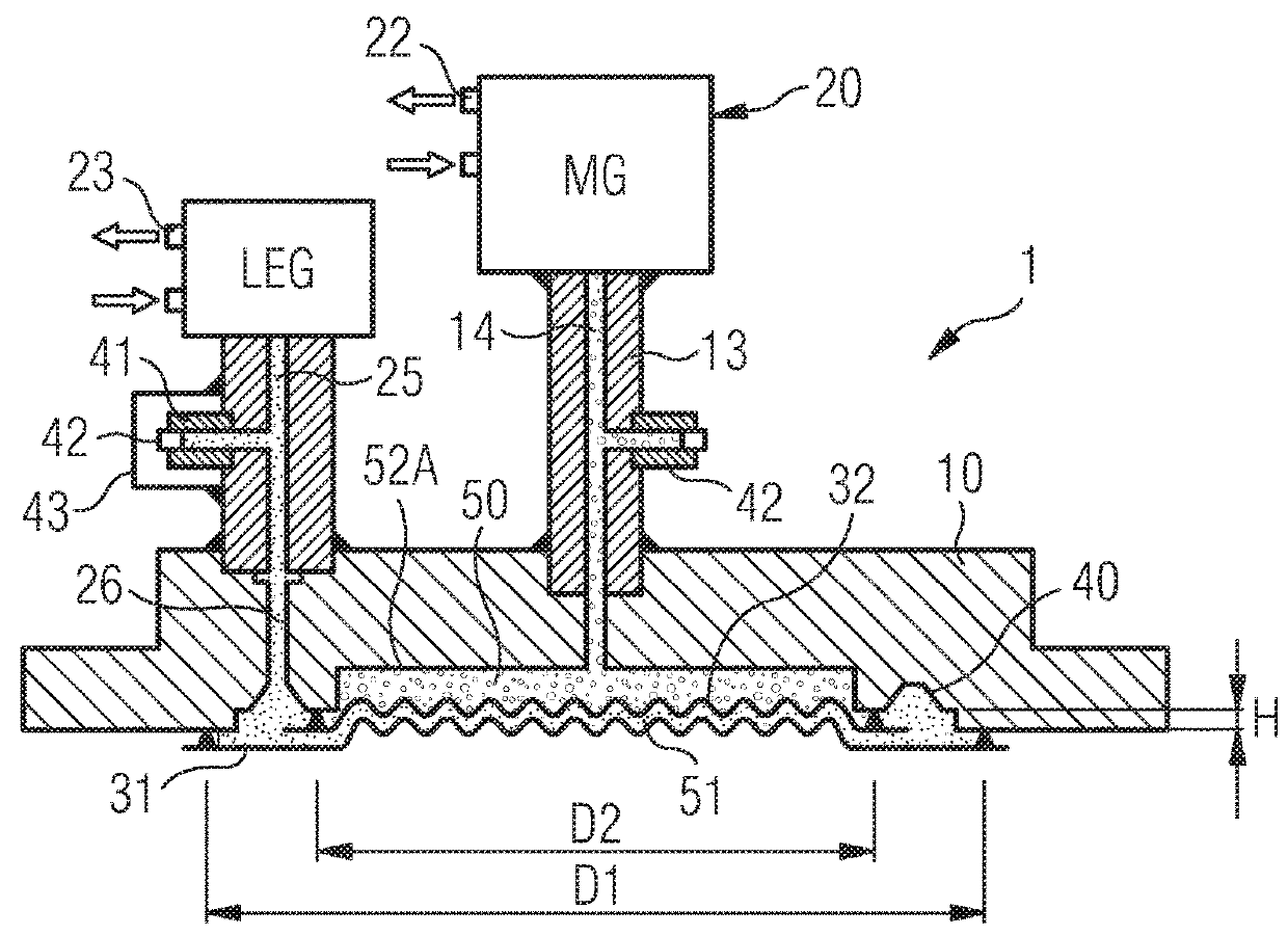
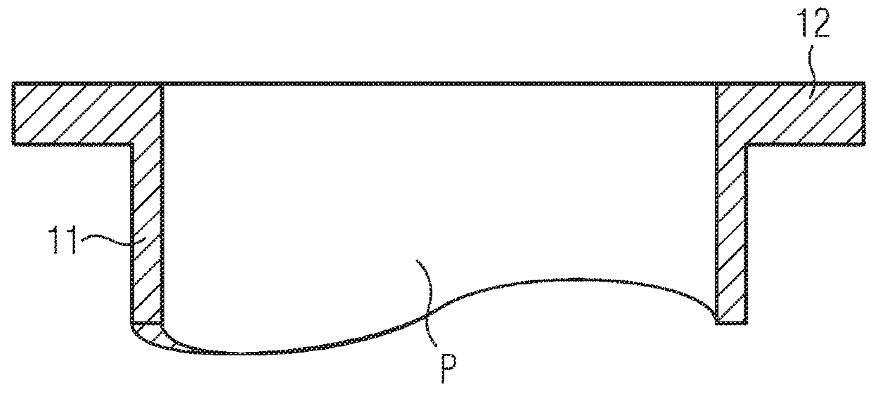
[0037]FIG. 1 shows a diaphragm seal assembly 1 according to the invention according to a first preferred embodiment, before a base body 10 of diaphragm seal assembly 1 is connected to a process chamber P to be monitored. Diaphragm seal assembly 1 illustrated in FIG. 1 mainly comprises base body 10, which is essentially disk-shaped, preferably in the form of a flange, which is connectable by a thread or via a clamp connection, a screw connection or the like to a sealing flange 11 of a connecting piece 12 of process chamber P, in which a process medium (not illustrated) to be monitored is present. Base body 10 may be made from a metallic material, for example from an austenitic steel. Alternatively, however, a design made from a plastic material, for example a fluoropolymer, may also be considered. In the assembled or mounted state, base body 10 terminates tightly with sealing flange 12 for the purpose of being able to receive a pressure of the process medium without falsification. On...


PUM


Abstract

A diaphragm seal assembly, which includes a measuring instrument, a pressure being transmitted from a process side to be monitored, via an arrangement of two diaphragms having an evacuated intermediate space disposed therebetween, to the measuring instrument, reliably separated from the process side, the fatigue strength of the diaphragm seal assembly under extreme application conditions being improved.

Description

[0001]This nonprovisional application claims priority under 35 U.S.C. § 119(a) to German Patent Application No. 10 2016 015 447.0, which was filed in Germany on Dec. 24, 2016, and which is herein incorporated by reference.BACKGROUND OF THE INVENTIONField of the Invention[0002]The present invention relates to a pressure measuring device or a diaphragm seal assembly for a pressure measuring device, comprising a pressure measuring element which is made, for example, from a tube, for example a Bourdon tube, or a sensor diaphragm. The pressure transmission takes place from one side of a process medium or process fluid to be monitored via a diaphragm seal, which keeps the process medium separate from a pressure measuring element path, whereby a fatigue strength of the pressure measuring instrument may be improved. Accordingly, a diaphragm seal is essentially used to transmit a process pressure, i.e. a pressure to be measured of the process medium, to a pressure measuring device, which inc...

Claims


Application Information

Patent Timeline
IPC IPC(8): G01L19/06G01L9/00G01M3/26G01L21/08
CPCG01L19/0672G01L9/0044G01M3/26G01L19/0645G01L21/08G01L7/041G01L7/043G01L7/048G01L7/04G01L19/06G01L19/0046G01M3/283G01L13/026
Inventor ZIPP, JOACHIMROSENBERGER, UDOPAULING, TORSTENKERN, HEIKOKALISCH, ALBRECHTHOERNING, UDO
Owner WLKA ALEXANDER WIEGAND SE & CO KG
Why Eureka
Try Eureka