
Cross flow fan for wide aircraft fuselage

a technology for aircraft fuselage and fan, which is applied in the direction of air-flow influencers, machines/engines, etc., can solve the problems of drag problems along the wide fuselage and achieve the effect of reducing the air boundary layer

Active Publication Date: 2018-06-07
RTX CORP
View PDF1 Cites 5 Cited by
  • Summary
  • Abstract
  • Description
  • Claims
  • Application Information

AI Technical Summary

Benefits of technology

The patent is for a fan that helps reduce the air that creates drag in aircraft with a wide fuselage. It does this by using a cross flow fan to move the air away from the outer edges of the aircraft. This results in less drag and allows for better performance.

Problems solved by technology

In such an aircraft body, boundary layer air along the wide fuselage creates drag issues.

Method used


Image

  • Cross flow fan for wide aircraft fuselage
  • Cross flow fan for wide aircraft fuselage
  • Cross flow fan for wide aircraft fuselage

Examples


Embodiment Construction

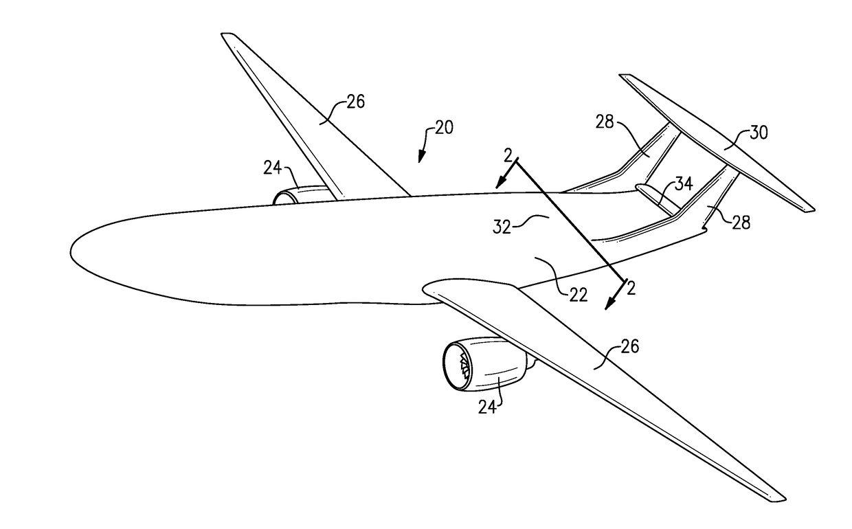
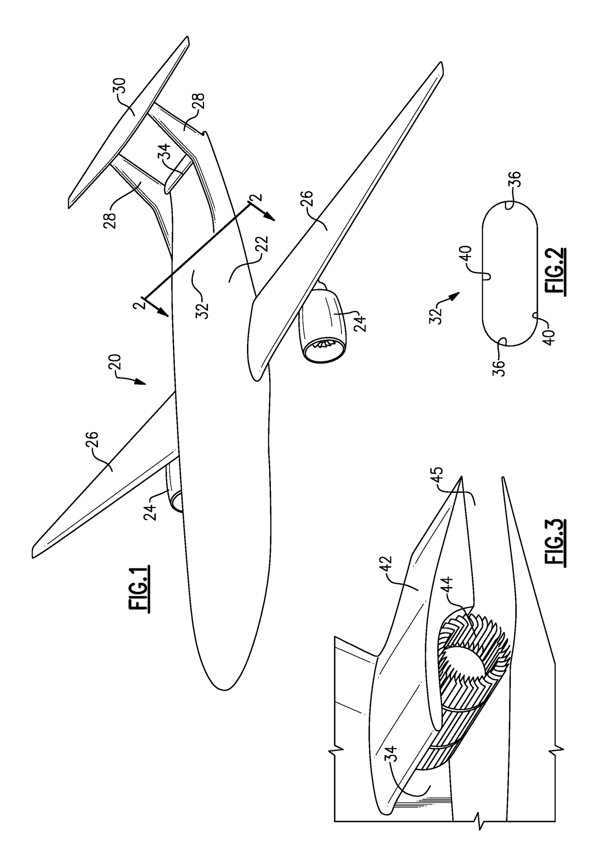
[0037]FIG. 1 shows an aircraft body 20 having a fuselage 22 and engines 24 mounted beneath wings 26. The aircraft body 20 is a so-called “double-bubble” aircraft body. Rear stabilizers 28 lead to a tail 30. A fuselage area 32 on top of the aircraft forward of the tail 30 is relatively wide and boundary layer air across the wide fuselage raises drag issues. As such, in this disclosure, an air intake 34 leads to a cross flow fan to energize this boundary layer air.

[0038]FIG. 2 is a cross-sectional view along line 2-2 of FIG. 1. The fuselage is not generally cylindrical in cross section. This differs from the prior art conventional tube+wing aircraft in which the fuselage is basically a cylindrical tube. The noncylindrical fuselage has a horizontal width significantly greater than its vertical height. This configuration may be achieved with a double bubble, which is essentially two cylinders blended together in the horizontal direction, or more generally any elongated or elliptical cro...


PUM


Abstract

A cross flow fan to be incorporated into an aircraft fuselage comprises an ingestion fan rotor to be positioned in a tail section of an aircraft fuselage to reduce boundary layer air from a top surface of the fuselage and to drive the air away from the top surface, and a drive arrangement for the ingestion fan rotor. An aircraft is also disclosed.

Description

CROSS-REFERENCE TO RELATED APPLICATIONS[0001]This disclosure is a continuation in part of U.S. patent application Ser. No. 15 / 072,267 filed Mar. 17, 2016.BACKGROUND OF THE INVENTION[0002]Aircraft bodies have been proposed that have a so-called “double-bubble” fuselage near the tail. In such bodies, there are two part cylindrical sections on opposed sides, with an elongated intermediate section, such that the aircraft body is relatively wide.[0003]In such an aircraft body, boundary layer air along the wide fuselage creates drag issues.[0004]It is been proposed to place the gas turbine engines for the aircraft in the fuselage and forward of the tail to utilize this air as part of the air for the gas turbine engines.[0005]However, other engine locations may be desirable.SUMMARY OF THE INVENTION[0006]This application relates to a cross flow fan to reduce boundary layer air that would otherwise create drag in proposed aircraft bodies having a relatively wide fuselage.[0007]In a featured ...

Claims


Application Information

Patent Timeline
Patent Type & Authority Applications(United States)
IPC IPC(8): B64D35/08B64C11/00B64C21/06B64C39/00B64D35/02B64C1/06
CPCB64D35/08B64C11/006B64C21/06B64C39/005B64D35/02B64C1/068F04D17/04B64D27/02B64D41/00B64C5/02B64C2230/04Y02T50/10B64C21/01B64D35/022B64D35/024B64C23/02
Inventor SUCIU, GABRIEL L.CHANDLER, JESSE M.LORD, WESLEY K.
Owner RTX CORP
Learn More