Retrofit Self-Annunciating Sprinkler

a self-annunciation, sprinkler technology, applied in the direction of sirens, instruments, musical instruments, etc., can solve the problems of inconvenient installation, high installation cost, and inability to meet the needs of professional installation, etc., to achieve convenient positioning, low cost, and simple installation

Inactive Publication Date: 2018-05-24
AKERS WILLIAM E
View PDF0 Cites 3 Cited by
  • Summary
  • Abstract
  • Description
  • Claims
  • Application Information

AI Technical Summary

Problems solved by technology

The costs can be prohibitive in some cases.
While rarely present in a residential setting, commercial sprinkler systems are available but require substantial capital and must be installed by certified professionals.
The system is expensive and complex to install.
The Stager and Stevens et al. devices are disadvantageous for a number of reasons, including that multiple devices are necessary to protect against fire from multiple burners and that the devices would be ineffective in the event of an oven fire.

Method used


Image

  • Retrofit Self-Annunciating Sprinkler
  • Retrofit Self-Annunciating Sprinkler
  • Retrofit Self-Annunciating Sprinkler

Examples


embodiment 11

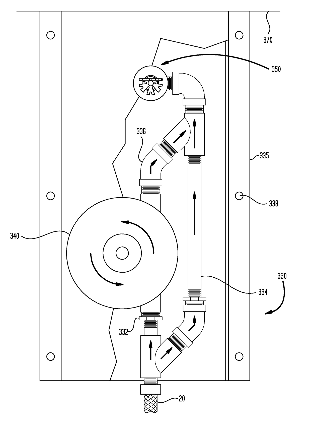
[0092]Embodiment No. 12 is the water-powered residential fire suppression system of Embodiment 11, wherein the unclosable multi-port coupling, the transfer line and the housing assembly have an absence of shutoff valves, thereby avoiding accidental disabling of the device.

[0093]Embodiment No. 13 is the water-powered residential fire suppression system of Embodiment No. 10, wherein the sprinkler head is provided with a deflector adapted to direct discharged water in a preferred direction.

[0094]Embodiment No. 14 is the water-powered residential fire suppression system of Embodiment No. 10, wherein the system further comprises a water-activated annunciator mounted to the housing, the water-activated annunciator having an inlet port and an outlet port, such that the inlet port of the water-activated annunciator is fastened to the fire-resistant transfer line and the outlet port of the water-activated annunciator is fastened to the sprinkler head.

[0095]Embodiment No. 15 is the water-powe...

embodiment 10

[0101]Embodiment No. 21 is the water-powered residential fire suppression system of Embodiment 10, wherein the housing assembly comprises fastening means to securely fasten the housing assembly to a wall, post, column, or ceiling.

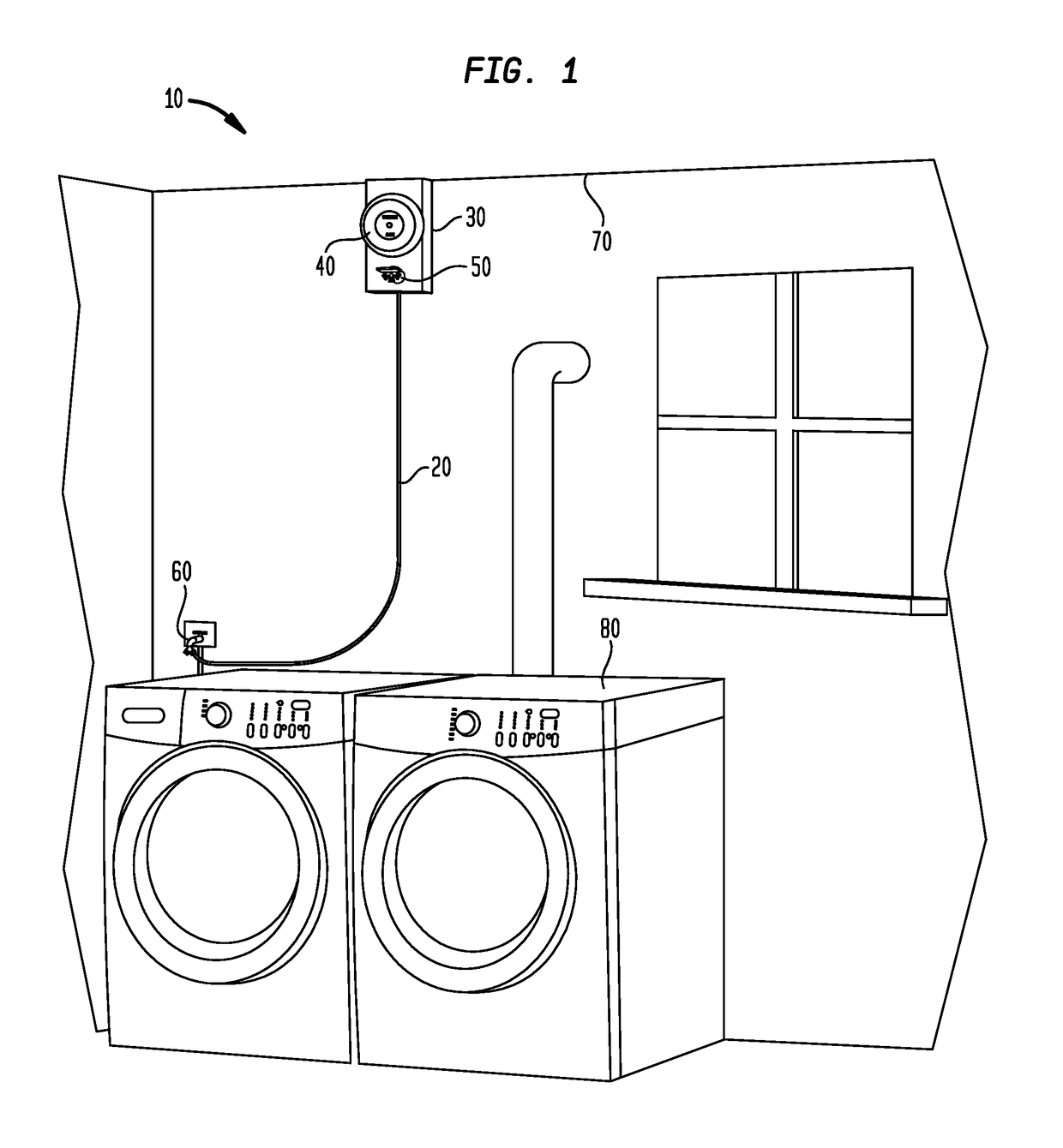
[0102]Embodiment No. 22 is a method of extinguishing a residential fire, comprising:[0103](a) installing the water-powered residential fire suppression system of Embodiment No. 10 at a ceiling-to-wall joint above a household appliance that upon operation emits heat, and[0104](b) fastening the fire resistant transfer line assembly to an existing water supply;[0105]whereby, when the sprinkler head is activated to allow flow therethrough, water flows through the transfer line onto the household appliance, thereby extinguishing a local fire.

[0106]Embodiment No. 23 is the method of Embodiment No. 22, wherein the household appliance is at least one selected from the group consisting of: a clothes dryer; a water heater; and a furnace.

[0107]Embodiment No. 24 is a w...


PUM


Abstract

A water-powered residential fire suppression and alarm system is provided. The system comprises a sprinkler head, a water-powered or electrically-powered alarm, a fire-resistant transfer line assembly, and a housing assembly. The sprinkler activates upon excessive heat. The transfer line assembly provides an unclosable channel connecting an existing residential water source with the sprinkler head. The transfer line assembly includes a fire-resistant transfer line connected to a multi-port coupling which connects to the existing water source. The transfer line assembly also provides water to the alarm. The housing assembly has a housing with a vertical span of about 3-12 inches. The sprinkler head and alarm are mounted to the housing assembly and the transfer line assembly is connected to the housing assembly. When water is provided to the coupling and the sprinkler head activates, water flows through the transfer line, activating the alarm.

Description

CLAIM FOR PRIORITY[0001]This patent application is a Continuation-in-Part of U.S. Nonprovisional patent application Ser. No. 15 / 595,278, filed on May 15, 2017, now U.S. Pat. No. ______. U.S. Nonprovisional patent application Ser. No. 15 / 595,278 is a Continuation-in-Part of U.S. Nonprovisional patent application Ser. No. 15 / 149,018, filed on May 6, 2016, now U.S. Pat. No. 9,672,712. The priorities of application Ser. Nos. 15 / 595,278 and 15 / 149,018 are hereby claimed and their disclosures are incorporated by reference in their entireties.FIELD OF INVENTION[0002]The present invention is drawn to a fire detection and extinguishing device that utilizes existing water sources, preferably affixed to a wall proximate a range installation. In some embodiments, the device is provided with a self-contained extinguishing material.BACKGROUND OF THE INVENTION[0003]As of 2013, residential fires in the U.S. caused an estimated 2,755 deaths, 12,450 injuries, and losses of more than $6.8 billion. (Se...

Claims


Application Information

Patent Timeline
Patent Type & Authority Applications(United States)
IPC IPC(8): G08B17/06A62C3/00A62C37/11A62C35/60G10K5/00G10K1/00
CPCG08B17/06A62C3/006A62C37/11A62C35/605G10K5/00G10K1/00G08B7/06G08B21/20G08B25/10G10K1/068G10K7/00
Inventor AKERS, WILLIAM E.
Owner AKERS WILLIAM E
Why Eureka
Try Eureka