
Tristate and cross current free output buffer

a cross-current free output buffer technology, applied in the field of data and signal processing, can solve the problems of semiconductor elements that may deviate or differ from a functional or expected behavior, drop and/or drive strength loss, and the semiconductor elements may not be desired to behave or malfunction

Active Publication Date: 2018-05-17
TESAT SPACECOM
View PDF2 Cites 0 Cited by
  • Summary
  • Abstract
  • Description
  • Claims
  • Application Information

AI Technical Summary

Benefits of technology

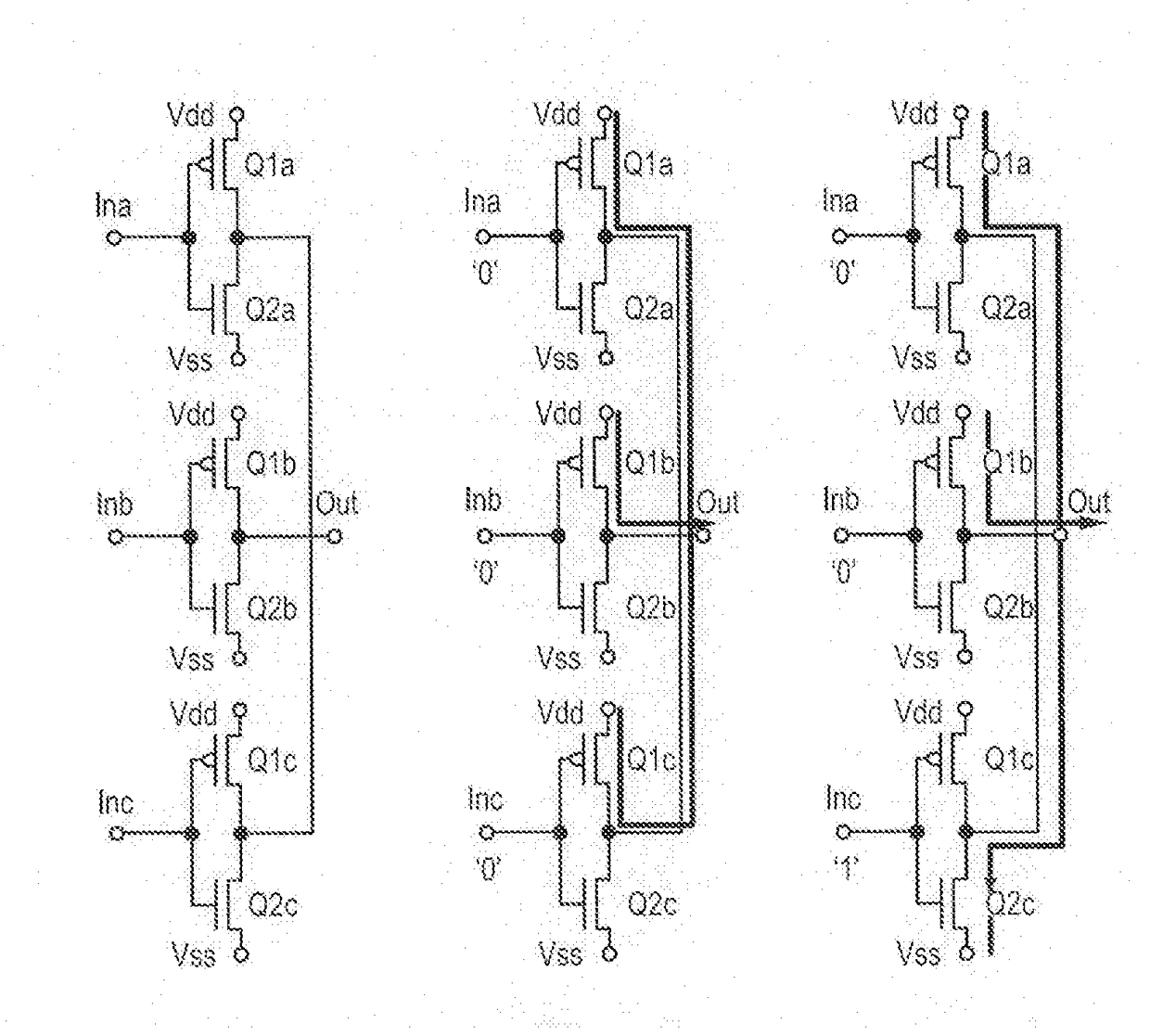
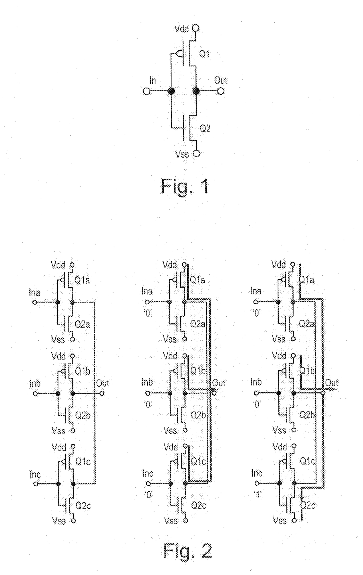
The output buffer described in this patent has multiple semiconductor elements arranged between the output port and the supply port, as well as between the output port and the ground port. This arrangement and controlling of the semiconductor elements increases safety against incorrect connections and reduces the likelihood of cross currents and voltage drops. The output buffer is also designed to be a tristate output buffer, which further improves certainty in level detection. Additionally, the design reduces radiation-related effects and avoids cross currents in outer space, ensuring reliable performance.

Problems solved by technology

Typically, redundant data processing is utilized in safety-related applications or in environments that are susceptible to malfunctioning (prone to breakdown), that is if either a high standard is placed to reliability of a result of a processing step or if failures or malfunctions cannot be avoided or are to be expected due to the operation environment.
Electronic circuits, in particular circuits that are built up at least in part with semiconductor elements, may be exposed to radiation under conditions in outer space out of the earth's atmosphere, which radiation may result in undesired behavior or malfunction of the semiconductor elements.
In particular, it may happen that under the influence of such radiation the behavior of the semiconductor elements may deviate or differ from a functional or expected behavior.
Here, the output buffers may be a residual sensitive part as these, in turn, may be susceptible to malfunctioning or may have an impact on voltage drops and / or drive strength losses (drop of the current provided at the output interface).

Method used


Image

  • Tristate and cross current free output buffer
  • Tristate and cross current free output buffer
  • Tristate and cross current free output buffer

Examples


Embodiment Construction

[0053]The following detailed description is merely illustrative in nature and is not intended to limit the embodiments of the subject matter or the application and uses of such embodiments. As used herein, the word “exemplary” means “serving as an example, instance, or illustration.” Any implementation described herein as exemplary is not necessarily to be construed as preferred or advantageous over other implementations. Furthermore, there is no intention to be bound by any expressed or implied theory presented in the preceding technical field, background, brief summary or the following detailed description.

[0054]FIG. 1 shows a single inverting output buffer which is designed as a CMOS output buffer in this example. The output buffer is made of two driver transistors Q1 and Q2 which are driven inversely and, hence, establish a connection of the output port Out either to the positive supply voltage Vdd or to ground Vss.

[0055]One can easily recognize in FIG. 1 that normally and in an...


PUM


Abstract

A tristate output buffer includes a first branch with a first buffer, and a second branch with a second buffer. The first buffer includes a supply port, a ground port, an output port, two switchable semiconductor elements of a first type, and two switchable semiconductor elements of a second type. Switching behavior of the switchable semiconductor elements of the first type differs from switching behavior of the switchable semiconductor elements of the second type. The two switchable semiconductor elements of the first type are connected in series and are between the supply port and the output port such that they can be put in a conductive state independent of each other. The two switchable semiconductor elements of the second type are connected in series and are between the ground port and the output port such that they can be put in a conductive state independent of each other.

Description

CROSS-REFERENCE TO PRIORITY APPLICATION[0001]This application claims the benefit of, and priority to, German patent application number DE 102016121696.8, filed Nov. 11, 2016. The content of the referenced application is incorporated by reference herein.TECHNICAL FIELD[0002]The present description relates to the field of data and signal processing, in particular to the field of redundant data and signal processing. A tristate output buffer is described which may be used in redundant data processing systems, for example. In addition, such a data processing system is provided, as well as a spacecraft like a communication satellite, for example, with such a data processing system.BACKGROUND[0003]Typically, redundant data processing is utilized in safety-related applications or in environments that are susceptible to malfunctioning (prone to breakdown), that is if either a high standard is placed to reliability of a result of a processing step or if failures or malfunctions cannot be avo...

Claims


Application Information

Patent Timeline
IPC IPC(8): H04B1/74H04B7/185
CPCH04B1/74H04B7/18515H03K19/003H03K19/00338H03K19/00392H03K19/007H03K19/0185H03K19/018521H03K19/094H03K19/09429H03K19/23
Inventor LUECK, VOLKER
Owner TESAT SPACECOM
Learn More