
Method and Apparatus for Producing Cement Clinker

a cement clinker and cement technology, applied in lighting and heating apparatus, separation processes, furnaces, etc., can solve the problems of increasing the oxygen content of the released exhaust gas, reducing and unable to meet the governmental emission limits, so as to reduce the oxygen content, increase the oxygen content, and reduce the oxygen content of the secondary and tertiary air.

Active Publication Date: 2018-05-10
SUDBAYERISCHES PORTLAND ZEMENTWERK GEBR WIESBOCK & CO
View PDF3 Cites 2 Cited by
  • Summary
  • Abstract
  • Description
  • Claims
  • Application Information

AI Technical Summary

Benefits of technology

The invention aims to provide a more efficient and cost-effective way to cool the exhaust gas from a cement clinker manufacturing process. The technical effect is to reduce the amount of exhaust gas that needs to be treated, which benefits from previously cooled exhaust gas and avoids the addition of oxygen through the cooling step. This results in a reduction in energy consumption and improved efficiency of the overall manufacturing process.

Problems solved by technology

Thus providing chloride bypass exhaust gas to the clinker cooler has the disadvantage that the oxygen content of the secondary and tertiary air is reduced.
Alternatively, the chloride bypass exhaust may be released with the main exhaust gas flow, but as the bypass exhaust gas is a mixture of air and flue gases it increases the oxygen content of the released exhaust gas, making it difficult if not impossible to comply with the governmental emission limits.
This augmented volume causes significant costs, because the dimensioning of the exhaust gas treatment means has to be increased accordingly.
Another disadvantage is that the mixing step with fresh air at ambient temperature significantly reduces the exergy of the chloride bypass gas and thus the amount of energy that can be recuperated and provided to heat sinks in the cement clinker manufacturing line.

Method used


Image

  • Method and Apparatus for Producing Cement Clinker
  • Method and Apparatus for Producing Cement Clinker
  • Method and Apparatus for Producing Cement Clinker

Examples


Embodiment Construction

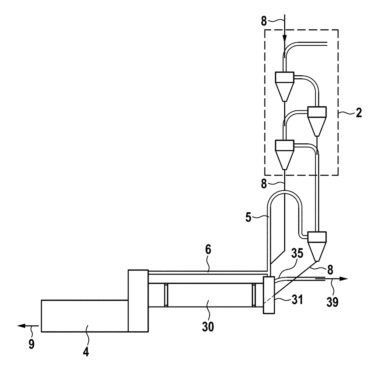
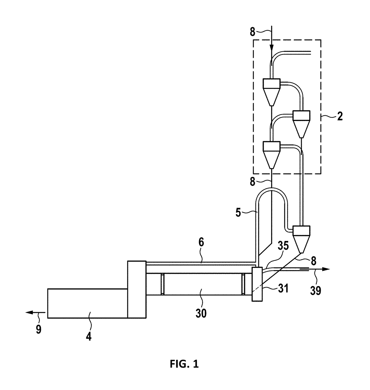
[0031]The cement clinker line in FIG. 1 comprises as usual a preheater 2, a kiln 30 and a clinker cooler 4. Raw meal 8 is preheated in the preheater 2 and provided to the kiln inlet 31. In the kiln 30 the raw meal 8 is calcined and sintered to clinker. The clinker 9 is discharged on the clinker cooler 4 and can be further processed after being cooled down (indicated by an arrow, symbolizing the clinker 9), e.g. by milling. Hot air from the clinker cooler 4 is provided to the kiln 30 as secondary air and leaves the kiln 30 at its inlet 31 as flue or exhaust gas. Said kiln exhaust gas is dust loaden and hot (˜typically 1500° C. to 2000° C.). The main amount of the kiln exhaust gas is provided to the preheater 2 for pre-warming the raw meal 8. Optionally a calciner 5 may be installed between the preheater 2 and the kiln 30. In that case the raw meal 8 is provided from the preheater 2 to the calciner 5 and from the calciner 5 to the kiln 30. At least a part of the kiln exhaust gas may b...


PUM

PropertyMeasurementUnit
temperature T1aaaaaaaaaa
temperature T2aaaaaaaaaa

Abstract

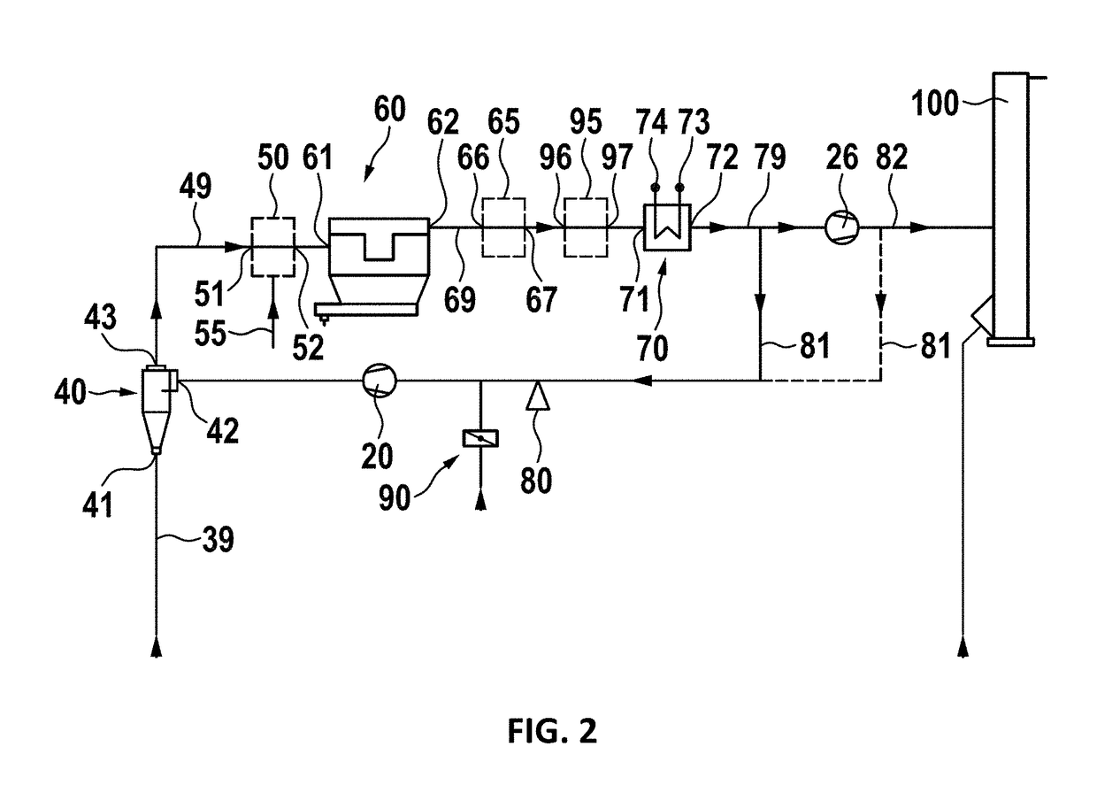
In methods of and / or plants for manufacturing cement clinker, the amount of chloride bypass exhaust gas 79 can be substantially decreased, when using previously cooled chloride bypass exhaust gas 81 and / or cooled kiln exhaust gas as coolant for the chloride bypass exhaust gas 39 prior to deducting the chloride bypass exhaust gas 39.

Description

PRIORITY CLAIM[0001]This application is a continuation of pending International Application No. PCT / EP2016 / 065785 filed on Jul. 5, 2016, which designates the United States and claims priority from European Application No. 15176157.4 filed on Jul. 9, 2015, both of which applications are incorporated by reference.BACKGROUND OF THE INVENTION1. Field of the Invention[0002]The invention relates to the field of cement clinker manufacturing, in particular to a method for removal of chlorine from the clinker process. First, a chloride bypass gas flow is provided by drawing of a fraction of a main exhaust gas flow. Said bypass gas flow is cooled in a first cooling step by mixing it with a cooling gas. Subsequent deducting removes the chlorine from the chloride bypass gas flow. The remaining heat may be recuperated by cooling the dedusted chloride bypass gas flow in a second cooling step by providing a thermal contact of the dedusted chloride bypass gas flow with at least one heat carrier flu...

Claims


Application Information

Patent Timeline
Patent Type & Authority Applications(United States)
IPC IPC(8): C04B7/47C04B7/36C04B7/44B01D53/86B01D53/90B01D53/00F27B7/20F27D17/00
CPCC04B7/475C04B7/47C04B7/364C04B7/44B01D53/8659B01D53/90B01D53/002B01D53/8628F27B7/2016F27D17/008B01D2251/2062B01D2251/2065B01D2255/20707B01D2255/20723B01D2255/20769B01D2255/20776B01D2255/50B01D2255/915B01D2257/2025B01D2257/404C04B7/60C04B2290/20Y02P40/121C04B7/365
Inventor LEIBINGER, HELMUT
Owner SUDBAYERISCHES PORTLAND ZEMENTWERK GEBR WIESBOCK & CO
Learn More