
Processing apparatus, processing system, image pickup apparatus, processing method, and storage medium

Active Publication Date: 2018-03-29
CANON KK
View PDF0 Cites 4 Cited by
  • Summary
  • Abstract
  • Description
  • Claims
  • Application Information

AI Technical Summary

Benefits of technology

The present invention is related to a method and system for processing images, as well as an apparatus for taking images and a computer program for this purpose. The technical effect that this patent aims to achieve is to allow for highly precise identification of the normal plane of an object in a shadow boundary area.

Problems solved by technology

However, this method needs a complex apparatus, and has an insufficient precision of the obtained plane normal.
Since the photometric stereo method needs the luminance information of the object at the plurality of light source positions, the plane normal of the object cannot be correctly calculated given the luminance information at the light source positions at which no luminance information is observed due to the shadows and luminance or brightness saturation.
Hence, the plane normal calculating process using the threshold determination cannot correctly the plane normal of the object in the shadow boundary area.

Method used


Image

  • Processing apparatus, processing system, image pickup apparatus,  processing method, and storage medium
  • Processing apparatus, processing system, image pickup apparatus,  processing method, and storage medium
  • Processing apparatus, processing system, image pickup apparatus,  processing method, and storage medium

Examples


first embodiment

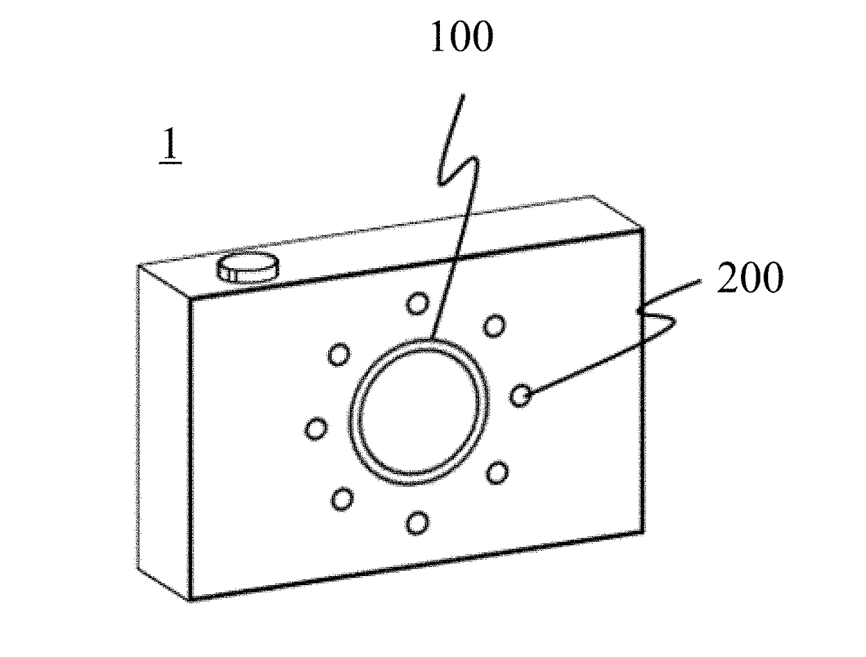
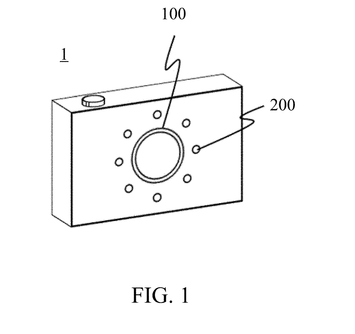
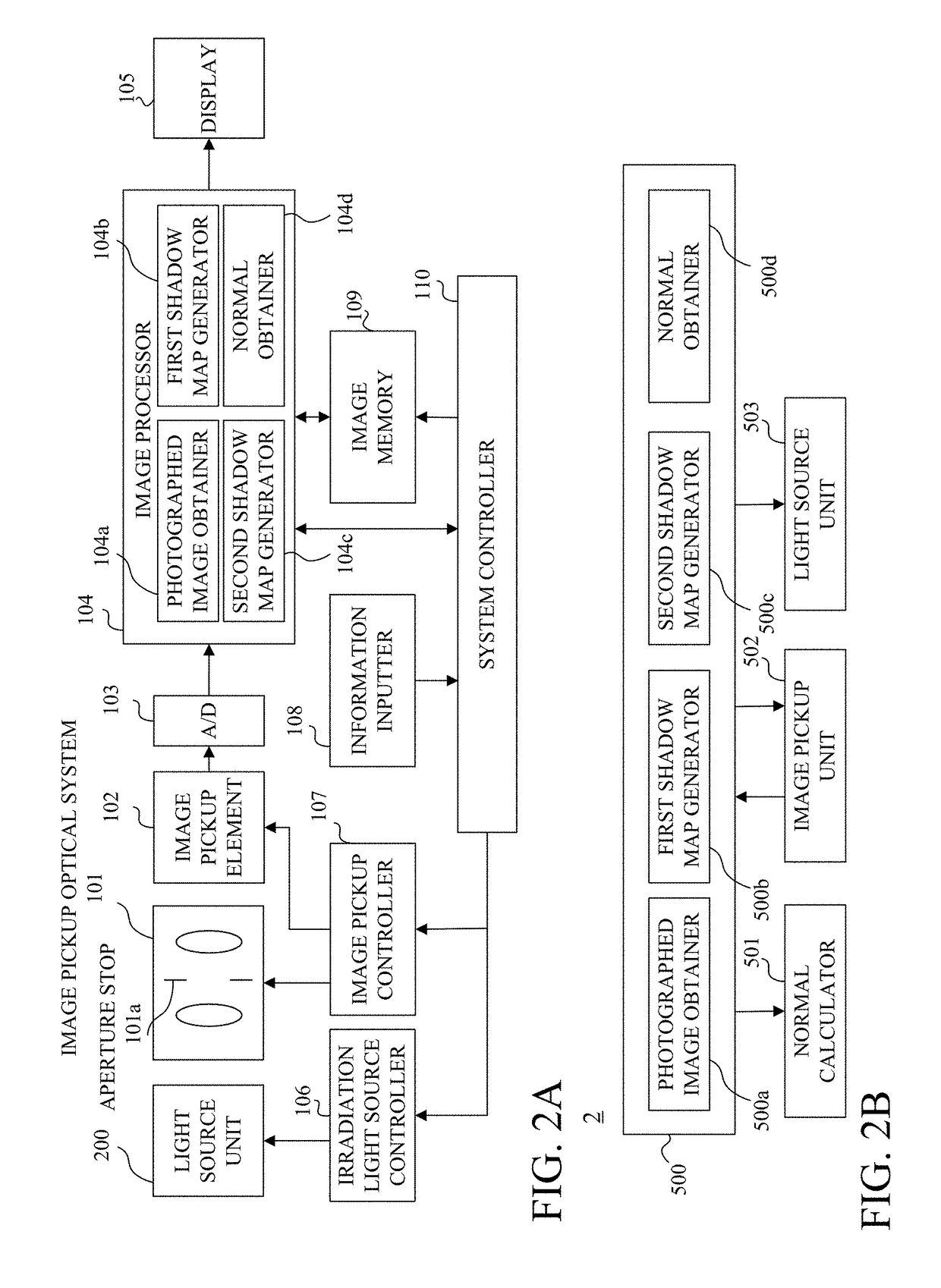
[0041]FIG. 1 is an overview of an image pickup apparatus 1 according to this embodiment. FIG. 2A is a block diagram of the image pickup apparatus 1. The image pickup apparatus 1 includes an image pickup unit 100 and a light source unit 200. The image pickup unit 100 includes an image pickup optical system 101. The light source unit 200 includes eight light sources concentrically arranged at regular intervals around the optical axis of the image pickup optical system 101 as a center. The photometric stereo method needs at least three light sources, and thus the light source unit 200 may include three or more light sources. While the light source 200 in this embodiment includes a plurality of concentrically arranged light sources around the light axis of the image pickup optical system 101 as a center, but the present invention is not limited to this embodiment. While this embodiment provides the light source unit 200 inside the image pickup apparatus 1, the light source unit 200 may ...

second embodiment

[0060]This embodiment describes a method for performing a dilation process based on a breath of the shadow boundary area estimated based on at least one of a three-dimensional position relationship (image pickup condition) among a light shield an object, and a light source, and the size of the light source (light source condition) as causes of the shadow, and for acquiring normal information. The image pickup apparatus in this embodiment is similar to that of the first embodiment, but needs three-dimensional position information of the object space and thus may include the following object distance calculator.

[0061]Referring now to FIG. 8, a description will be given of a plane normal calculating process according to this embodiment. FIG. 8 is a flowchart of the plane normal calculating process according to this embodiment. The plane normal calculating process is executed by the system controller 110 and the image processor 104 illustrated in FIG. 2A in accordance with the processin...

third embodiment

[0071]While the first and second embodiments describe an image pickup apparatus having a built-in light source, this embodiment describes a normal information acquiring system that includes an image pickup apparatus and a light source unit.

[0072]FIG. 14 is an overview of the normal information acquiring system. The normal information acquiring system includes an image pickup apparatus 301 configured to photograph an object 303, and a plurality of light source units 302. The image pickup apparatus 301 in this embodiment is similar to that of the first embodiment, but may not contain a plurality of light sources.

[0073]The light source unit 302 may be connected to the image pickup apparatus 301 through a wire or wirelessly, and controlled based on information from the image pickup apparatus 301. While the photometric stereo method needs photographed images by sequentially irradiating light from at least three light sources, at least one light source may be provided if the light source ...


PUM


Abstract

A processing apparatus includes a photographed image obtainer configured to obtain a plurality of photographed images of an object, the images being photographed by sequentially irradiating light onto the object from a plurality of different light source positions, a first shadow map generator configured to generate a first shadow map by determining a shadow area in the plurality of photographed images, a second shadow map generator configured to generate a second shadow map based on the first shadow map, and a normal information obtainer configured to obtain normal information of the object calculated based on the second shadow map and the plurality of photographed images.

Description

BACKGROUND OF THE INVENTIONField of the Invention[0001]The present invention relates to a processing method, a processing system, an image pickup apparatus, a processing method, and a storage medium.Description of the Related Art[0002]An image based on a physical model can be generated in image processing after image pickup by obtaining more physical information on an object. For example, an image in which a view of the object is varied can be generated. The view of the object is determined by shape information of the object, reflectance information of the object, light source information, etc. Since a physical behavior of light emitted from the light source and reflected by the object depends on a local plane normal, use of the plane normal of the object is particularly effective as shape information rather than the three-dimensional shape. One known method for obtaining the plane normal of the object is a method for converting into plane normal information a three-dimensional shap...

Claims


Application Information

Patent Timeline
IPC IPC(8): H04N5/235H04N5/225G06T7/586
CPCH04N5/2351H04N5/2256H04N5/2354G06T7/586H04N5/265H04N23/56H04N23/71H04N23/74
Inventor KUSUMI, YUICHIINOUE, CHIAKIIDA, YOSHIAKI
Owner CANON KK
Learn More