
Wire electric discharge machining apparatus

Active Publication Date: 2012-05-03
MITSUBISHI ELECTRIC CORP
View PDF52 Cites 2 Cited by
  • Summary
  • Abstract
  • Description
  • Claims
  • Application Information

AI Technical Summary

Benefits of technology

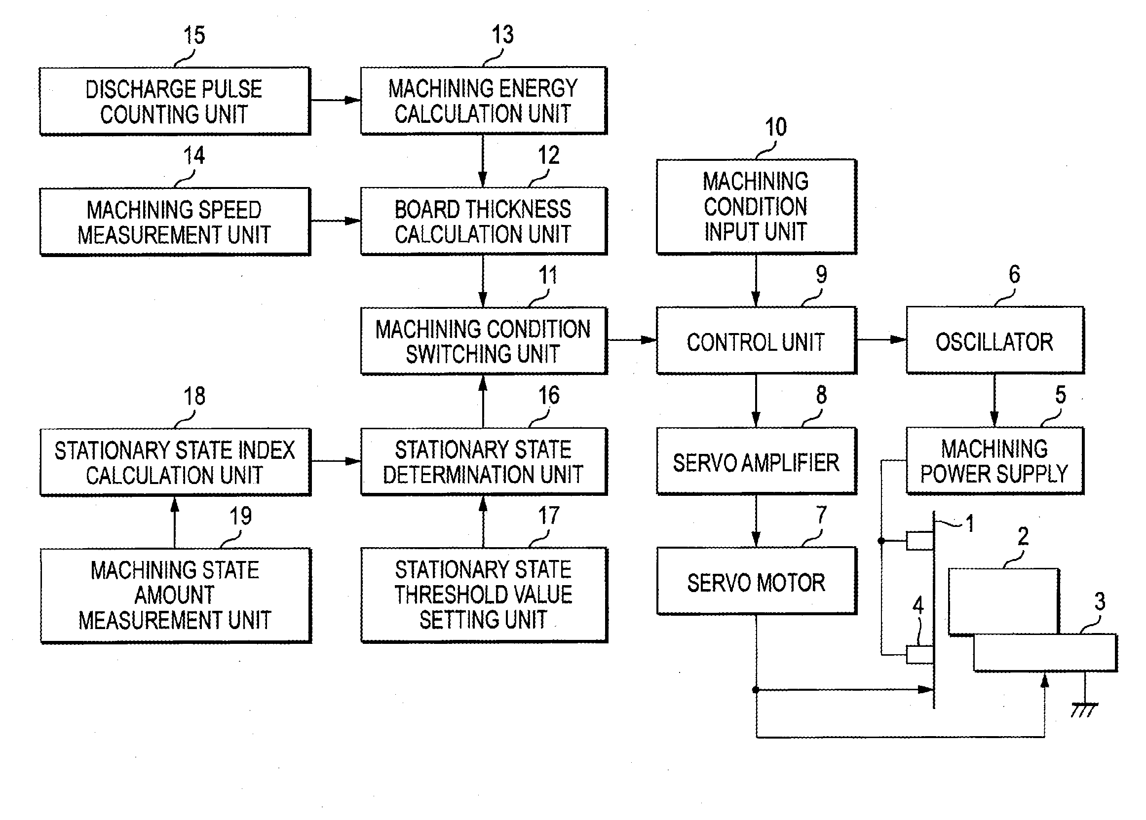
[0021]According to the invention, the stationary state determination unit can determine a transient state of the machining servo in which the board thickness may be falsely detected and a stationary state of the machining servo in which the board thickness can be precisely calculated.
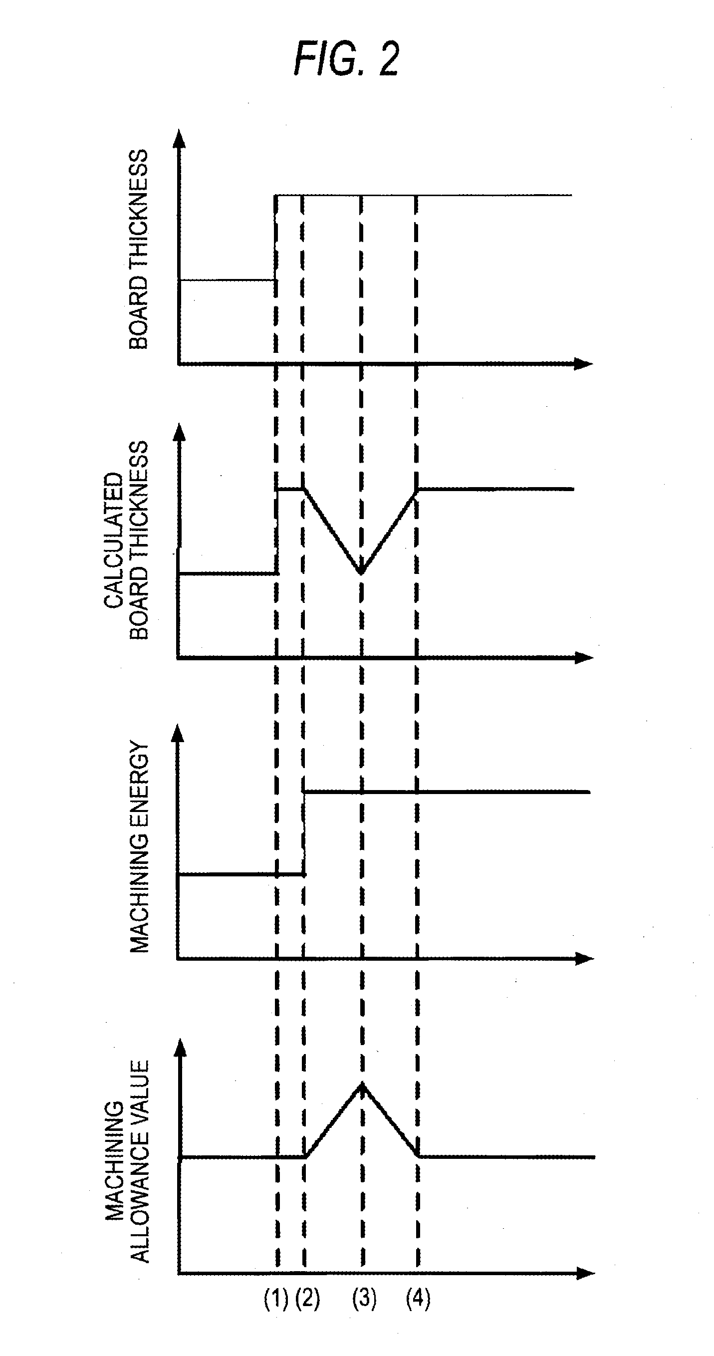
[0022]At the transient state in which the board thickness may be falsely detected, the apparatus waits for the switching of the machining condition corresponding to the calculated board thickness and switches the machining condition in accordance with the calculated board thickness after the board thickness can be precisely calculated at the stationary state. As a result, it is possible to avoid the switching to the inappropriate machining condition due to the false detection of the board thickness.

Problems solved by technology

This is because, although there is a limit on the machining current to be supplied to the wire electrode, as the workpiece becomes thicker, a current density per a unit wire electrode length becomes smaller, so that the wire breaking limit is increased.
In the meantime, when the board thickness exceeds a threshold value, the effects of removing machining powders and cooling the wire electrode by a machining liquid are deteriorated, so that the wire breaking limit is lowered and thus the wire may be broken down.

Method used


Image

  • Wire electric discharge machining apparatus
  • Wire electric discharge machining apparatus
  • Wire electric discharge machining apparatus

Examples


second embodiment

[0087]Before explaining operations of a second embodiment, a concept of the invention is first described.

[0088]Regarding a problem where an error is caused in the calculated board thickness due to the switching of the machining condition corresponding to the change of the board thickness, and the machining condition is switched to the inappropriate machining condition due to the error in the calculated board thickness, the first embodiment provides the technology of avoiding the inappropriate switching of the machining condition.

[0089]However, when the change of the board thickness is great, the difference of the machining energy of the machining condition switched before and after the change of the board thickness becomes large. Accordingly, it takes time after the machining condition is switched until the stationary state determination unit 16 determines that the machining servo is in the stationary state.

[0090]Regarding this, according to this embodiment, when the machining condi...


PUM

PropertyMeasurementUnit
Thicknessaaaaaaaaaa
Lengthaaaaaaaaaa
Currentaaaaaaaaaa

Abstract

A wire electric discharge machining apparatus that performs an electric discharge machining by applying a pulse voltage between a wire electrode (1) and a workpiece (2), the wire electric discharge machining apparatus including, a machining speed detection unit (14) that detects relative machining speed of the workpiece (2) and the wire electrode (1); a machining energy calculation unit (13) that calculates machining energy of a discharge pulse; a board thickness calculation unit (12) that calculates a board thickness of the workpiece (4) based on the machining speed detected by the machining speed detection unit (14) and the machining energy calculated by the machining energy calculation unit (13); a stationary state determination unit (16) that determines whether the machining is in a stationary state from a machining state during the machining, after the machining condition is switched in accordance with a board thickness of the workpiece (4) calculated by the board thickness calculation unit (12); and a machining condition switching unit (11) that switches the machining condition to a machining condition corresponding to a board thickness calculated by the board thickness calculation unit (12) when the stationary state determination unit (16) determines that the machining is in the stationary state and does not switch the machining condition to the machining condition corresponding to a calculated board thickness when the stationary state determination unit determines that the machining is not in the stationary state.

Description

TECHNICAL FIELD[0001]The present invention relates to a wire electric discharge machining apparatus.BACKGROUND ART[0002]In general, in a wire electric discharge machining, when a board thickness of a workpiece is within a range of 40 to 60 mm, a wire breaking limit of a wire electrode is the highest, so that it is possible to set a machining condition having the highest machining energy.[0003]This is because, although there is a limit on the machining current to be supplied to the wire electrode, as the workpiece becomes thicker, a current density per a unit wire electrode length becomes smaller, so that the wire breaking limit is increased. In the meantime, when the board thickness exceeds a threshold value, the effects of removing machining powders and cooling the wire electrode by a machining liquid are deteriorated, so that the wire breaking limit is lowered and thus the wire may be broken down.[0004]In other words, as described above, the inputtable energy becomes maximum when ...

Claims


Application Information

Patent Timeline
IPC IPC(8): B23H1/02
CPCB23H7/04B23H7/20B23H7/065
Inventor ONODERA, YASUOSHIOZAWA, TAKAHIROSATO, TATSUSHI
Owner MITSUBISHI ELECTRIC CORP
Learn More