
Substrate treating device and substrate treating method

a substrate and treating device technology, applied in the direction of cleaning process and apparatus, cleaning liquids, semiconductor/solid-state device testing/measurement, etc., can solve the problem of large change in the concentration of treating liquid during a lot treatment, and it is difficult in some cases to maintain a concentration in which the dissolution reaction to the etching progresses sufficiently

Active Publication Date: 2018-03-29
DAINIPPON SCREEN MTG CO LTD
View PDF7 Cites 5 Cited by
  • Summary
  • Abstract
  • Description
  • Claims
  • Application Information

AI Technical Summary

Benefits of technology

The present invention provides a method for stabilizing the concentration of a treating liquid within a treating tank, even when the quantity of an object to be etched dissolved by one etching treatment is large. This is achieved by recirculating the treating liquid from an outer tank to the inner tank and using a temperature adjuster and filtering unit to remove impurities and prevent rapid changes in the temperature of the treating liquid around the substrate. Additionally, an overflow pipe can be included to remove particles of impurities generated by etching.

Problems solved by technology

A concentration of the treating liquid in each treating tank of the substrate treating device changes in some cases, due to evaporation and decomposition of a treating-liquid constituent component, along with lapse of time.
In such a case, there is a large change in the concentration of a treating liquid during treating of a lot.
Therefore, it has been impossible in some cases to maintain a concentration in which dissolution reaction to the etching sufficiently progresses.

Method used


Image

  • Substrate treating device and substrate treating method
  • Substrate treating device and substrate treating method
  • Substrate treating device and substrate treating method

Examples


first embodiment

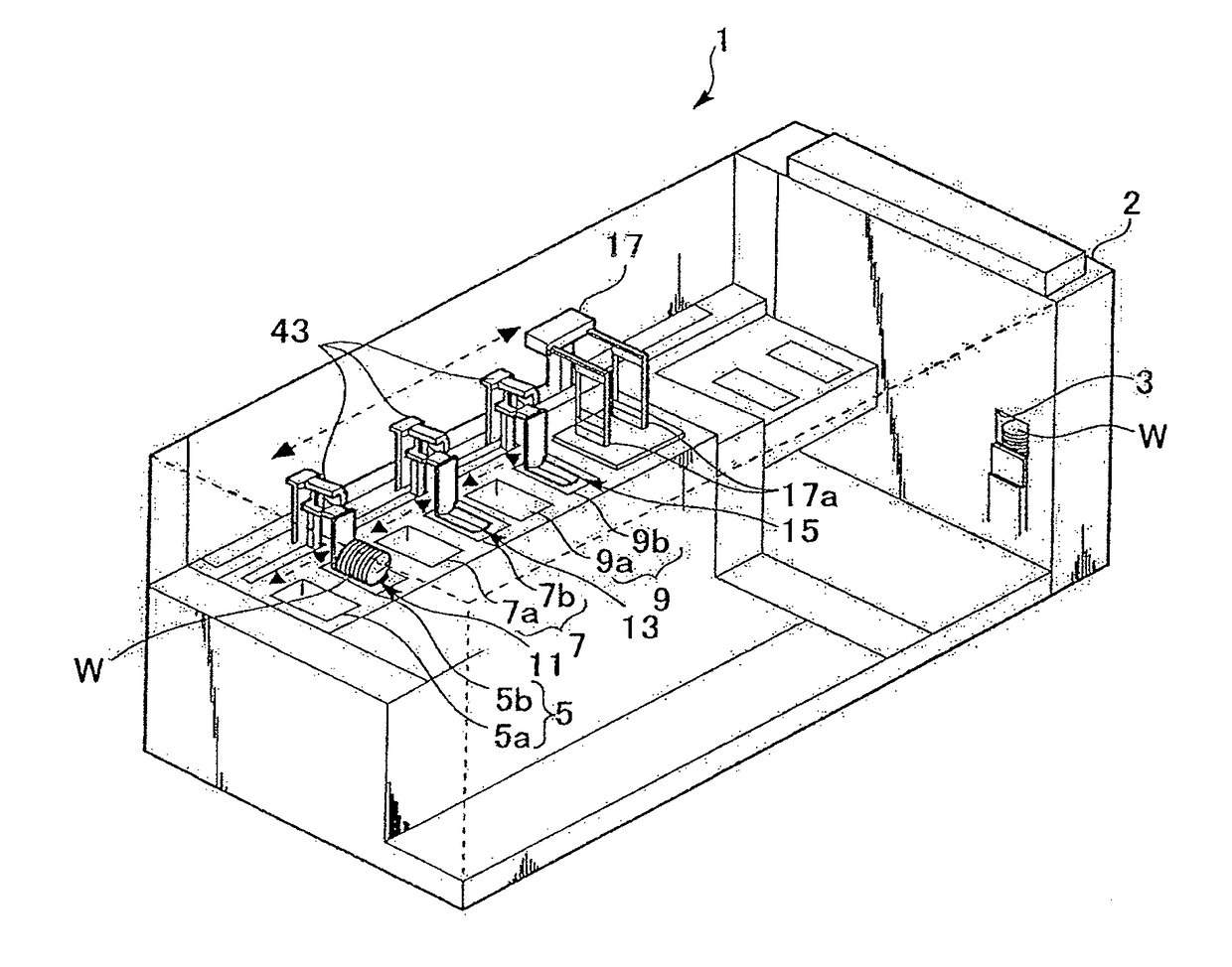
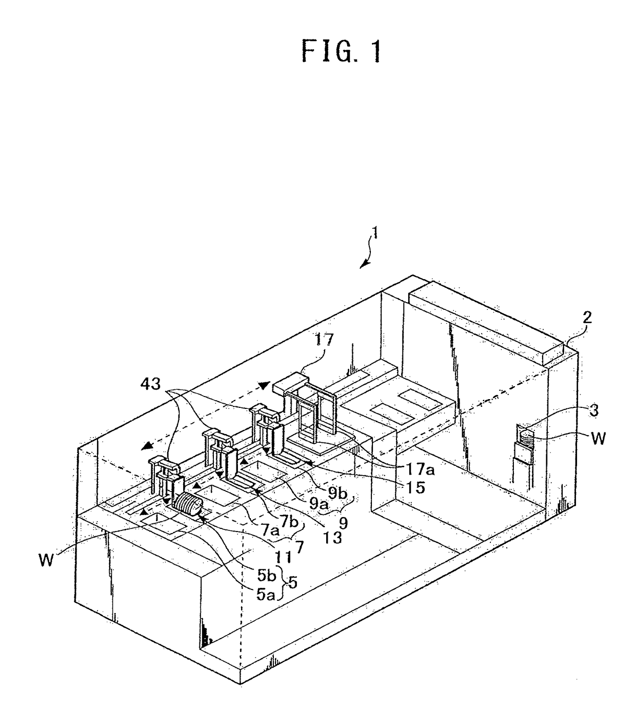
[0027]FIG. 1 is a perspective view showing a schematic configuration of a substrate treating device 1 according to a first embodiment. The substrate treating device 1 performs an etching treatment and a washing treatment (hereinafter, also simply referred to as a “treatment”) on mainly a substrate (for example, a semiconductor substrate) W. In the substrate treating device 1, a buffer section 2 that stocks the substrate W is disposed on a right depth side in FIG. 1. On a further right depth side of the buffer section 2, a front panel (not shown) for operating the substrate treating device 1 is provided. Further, on an opposite side of the front panel of the buffer section 2, a substrate carry-out port 3 is provided. Further, treating units 5, 7, and 9 that perform a treatment on the substrate W are arranged in parallel from an opposite side of the buffer section 2 (a left front side in FIG. 1) in a longitudinal direction of the substrate treating device 1.

[0028]The treating units 5,...

second embodiment

[0057]FIG. 5 is a treatment flowchart showing an example of a treatment according to a second embodiment. Because the treatments in S11 to S13 and S15 to S17 in FIG. 5 are similar to the treatments in S1 to S3 and S5 to S7 in FIG. 4, a description of the treatments in S11 to S13 and S15 to S17 in FIG. 5 will be omitted. In the present embodiment, when it is determined in S14 that a predetermined time has passed from the start of the treatment (S14: Yes), the substrate treating device 1 performs a partial-liquid replacement treatment (S15).

[0058]When the number of substrates to be treated in the batch treatment is known in advance, it is possible to forecast how long it will take from the start of the treatment before the concentration of the treating liquid deviates from a permissible range. The quantity of the treating liquid that requires replacement increases in proportion to the quantity of substrates to be treated. Therefore, in the present embodiment, a replacement quantity of...

third embodiment

[0060]In the example shown in FIG. 3, the adjacent treating tank 5b is utilized for the chemical-liquid supply source 41. Instead, the chemical-liquid supply source 41 may be configured to supply normal-temperature phosphoric acid manufactured in the factory to the treating tank 7a.

[0061]In the example shown in FIG. 3, the outlet ports of the chemical liquid line 42 and the pure water line 47 are provided near the inlet port of the circulation line 20 provided on the bottom surface of the outer tank 50b. The chemical liquid and the pure water that are additionally supplied are first drawn by a large quantity into the circulation line 20, and are supplied to the inner tank 50a after the temperatures of the chemical liquid and the pure water are raised by the temperature adjuster 22. Therefore, even when the normal-temperature chemical liquid and pure water are supplied to the outer tank50b, a temperature change in the inner tank 50a can be suppressed.


PUM


Abstract

The substrate treating device performs a predetermined treatment on a substrate by immersing the substrate into a treating liquid that contains a predetermined chemical liquid and pure water. Further, the substrate treating device includes a treating tank in which a treating liquid with which a predetermined treatment is performed on the substrate is stored, a supply unit that supplies a chemical liquid or pure water to the treating tank, a discharge unit that discharges the treating liquid stored in the treating tank, and a control unit that controls supply of the treating liquid or the pure water by the supply unit. The control unit causes the supply unit to supply the chemical liquid or the pure water during performing the predetermined treatment.

Description

CROSS-REFERENCE TO RELATED APPLICATION[0001]This application is based upon and claims the benefit of priority of the prior Japanese Patent Application No. 2016-185928, filed on Sep. 23, 2016 the entire contents of which are incorporated herein by reference.BACKGROUNDTechnical Field[0002]The present invention relates to a substrate treating device and a substrate treating method for performing an etching treatment and a washing treatment on a substrate of a semiconductor wafer and a relevant item by immersing the substrate into a treating tank. Particularly, the present invention relates to concentration control of a treating liquid in the treating tank.[0003]A manufacturing process of a semiconductor device includes a step of performing an etching treatment and a washing treatment on a substrate of a semiconductor wafer and a relevant item, by immersing the substrate into a treating tank. Such a step is performed by a substrate treating device that includes a plurality of treating t...

Claims


Application Information

Patent Timeline
Patent Type & Authority Applications(United States)
IPC IPC(8): H01L21/67H01L21/311H01L21/02H01L21/66B08B3/04
CPCH01L21/67023H01L21/67253H01L21/31111H01L21/02068H01L22/20B08B3/04H01L21/67086H01L21/6715H01L21/67017H01L21/67057H01L21/02052H01L21/30604H01L21/67248
Inventor SUGIOKA, SHINJI
Owner DAINIPPON SCREEN MTG CO LTD
Learn More