Clutch
- Summary
- Abstract
- Description
- Claims
- Application Information
AI Technical Summary
Benefits of technology
Problems solved by technology
Method used
Image

Examples
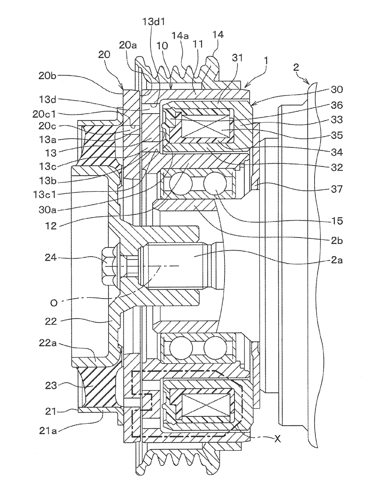
first embodiment
[0062]An electromagnetic clutch 1 of a first embodiment shown in FIG. 1 is used in a drive mechanism of a compressor 2. The drive mechanism of the compressor 2 rotates a compression mechanism when the drive mechanism receives a rotational drive force from an engine, which serves as a drive source that outputs a drive force for driving a vehicle. Therefore, in the present embodiment, the engine is the drive source, and the compressor 2 is a driven-side apparatus.
[0063]The compressor 2 suctions and compresses refrigerant. The compressor 2 cooperates with a radiator, an expansion valve and an evaporator to form a refrigeration cycle apparatus of a vehicle air conditioning system. The radiator radiates heat from the refrigerant, which is discharged from the compressor 2. The expansion valve depressurizes and expands the refrigerant, which is outputted from the radiator. The evaporator evaporates the refrigerant, which is depressurized by the expansion valve, to implement heat absorption...
PUM
| Property | Measurement | Unit |
|---|---|---|
| Thickness | aaaaa | aaaaa |
| Thickness | aaaaa | aaaaa |
| Force | aaaaa | aaaaa |
Abstract
Description
Claims
Application Information
 - R&D
- Intellectual Property
- Life Sciences
- Materials
- Tech Scout
- Unparalleled Data Quality
- Higher Quality Content
- 60% Fewer Hallucinations
Browse by: Latest US Patents, China's latest patents, Technical Efficacy Thesaurus, Application Domain, Technology Topic, Popular Technical Reports.
© 2025 PatSnap. All rights reserved.Legal|Privacy policy|Modern Slavery Act Transparency Statement|Sitemap|About US| Contact US: help@patsnap.com