
A sensor interface for interfacing with a sensor

a sensor and interface technology, applied in the field of sensor interfaces, can solve the problems of low battery life of the sensor, power consumption of the sensor, and inability to meet the needs of users, and achieve the effect of less writing and high power requirements

Active Publication Date: 2018-02-15
CAMLAB
View PDF2 Cites 7 Cited by
  • Summary
  • Abstract
  • Description
  • Claims
  • Application Information

AI Technical Summary

Benefits of technology

The patent text is about a way to save sensor data using less power. By using a certain type of memory, the writing and erasing of data can be done less frequently, which means that less power is needed to maintain the data. This helps to keep the device running for longer periods of time on less battery power.

Problems solved by technology

Known arrangements such as the many described above with separate sensors and meters with wireless communication between the meter and the sensor are power intensive.
In known arrangements, that use batteries for power, the battery life of the sensor is low.
While this is inconvenient in some sensor applications such as for domestic use it is acceptable.
However, for other applications such as for sensor use in remote areas for occasional readings from the sensor it is not acceptable.

Method used


Image

  • A sensor interface for interfacing with a sensor
  • A sensor interface for interfacing with a sensor
  • A sensor interface for interfacing with a sensor

Examples


Embodiment Construction

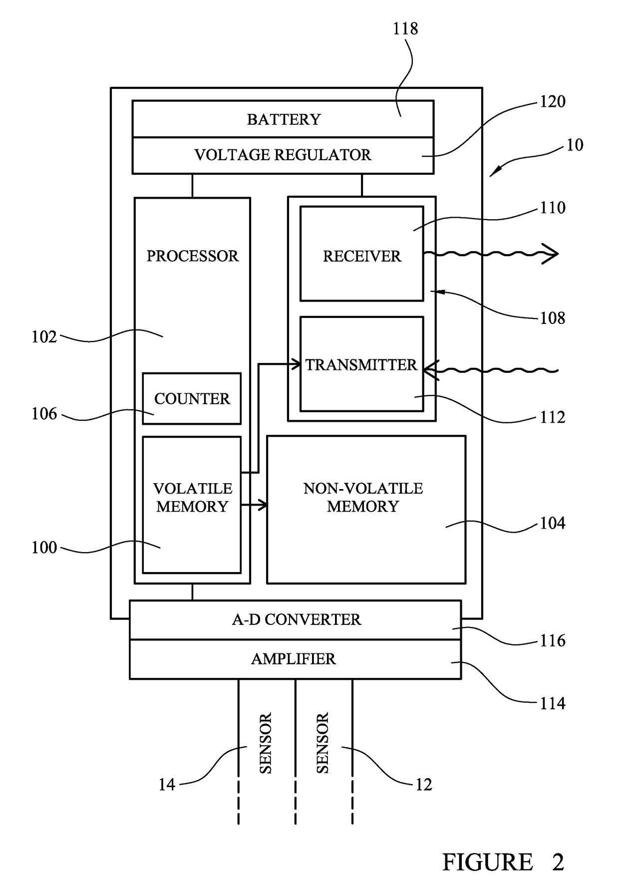
[0048]Example sensor interfaces 10 will now be described with reference to FIGS. 1 to 6.

[0049]In the example of FIG. 1, the sensor interface 10 for interfacing with a sensor 12,14 such as an electrochemical sensor, a temperature sensor or the like is illustrated connected to a pair of sensors in the form of an electrochemical sensor 12 and a temperature sensor 14. The sensors or probes are cylindrical with a circular cross-section having significantly greater length than diameter. The sensors are located next to one another and with their longitudinal axes parallel to one another. The sensors have an electrical connection at their proximal end. This electrical connection includes a conductor that forms an electrical connection to the electrode performing the sensing. In the example of FIG. 1, the distal end of the sensors are located in a chemical 16 whose properties are being measured by the sensors 12,14. Each of the sensors provide a millivolt output to the sensor interface givin...


PUM

PropertyMeasurementUnit
timeaaaaaaaaaa
volatileaaaaaaaaaa
volatile memoryaaaaaaaaaa

Abstract

A sensor interface for interfacing with a sensor such as an electrochemical sensor, a temperature sensor or the like in which the interface comprises a memory configured to store data received at the interface from a sensor. The sensor interface is configured to assess the difference between data values in the memory, and to transmit advertising packets at a rate dependent on the difference between the values. The sensor interface includes a volatile memory and a non-volatile memory. The volatile memory is configured to store data received at the sensor interface from a sensor. The non-volatile memory is configured to store data stored in the volatile memory. The sensor interface is configured such that: data received at the sensor is stored in the volatile memory forming stored data until the volatile memory is substantially full and then at least some of the stored data is transferred to the non-volatile memory.

Description

FIELD OF THE INVENTION[0001]The present invention relates to a sensor interface for interfacing with a sensor such as an electrochemical sensor (for example, for pH, ion-selective, dissolved oxygen, or conductivity measurement), a temperature sensor or the like typically to provide wireless communication for the sensor.BACKGROUND OF THE INVENTION[0002]Electric sensors are well known in the measurement and instrumentation industry. They are used widely in laboratories and in the field to measure physical and chemical properties of samples. A typical electric sensor is an electrochemical sensor such as pH, ion-selective, dissolved oxygen or conductivity electrode or a temperature sensor. They are available commercially in several different form factors.[0003]A meter may have both an electrochemical sensor and an electronic temperature sensor fitted to it. This is because the parameters being measured by the electrochemical sensor may be altered by the temperature of a solution under t...

Claims


Application Information

Patent Timeline
Patent Type & Authority Applications(United States)
IPC IPC(8): G01N27/28G06F12/02G06F12/06H04Q9/00
CPCG01N27/286H04Q9/00G06F12/0238G06F12/0638H04Q2209/43H04Q2209/88H04Q2209/826G06F2212/205G06F2212/202G11C11/005H04W52/0258Y02D10/00Y02D30/70G01N27/26G01N33/48785
Inventor SIMS, STEPHEN CHARLES
Owner CAMLAB
Learn More