
Control Method and Device for Circuit with a Bridge Arm of a Switch

a control method and switch technology, applied in the field of circuits, can solve the problems of increasing the loss of the auxiliary switch circuit, the inability to improve soft switching efficiency, and the increase of the frequency, so as to reduce the loss of the auxiliary switch, reduce the passive loss of lc resonance, and reduce the frequency

Active Publication Date: 2018-02-08
EMERSON NETWORK POWER CO LTD
View PDF4 Cites 6 Cited by
  • Summary
  • Abstract
  • Description
  • Claims
  • Application Information

AI Technical Summary

Benefits of technology

The present invention is about a circuit that reduces lost power and noise, improves harmonics and reduces the size of heat sinks. It uses a special type of carrier to optimize the switching of power devices, reducing stress and improving stability and efficiency. The invention can be used in various circuit designs, such as AC / DC or DC / AC circuits, and improves control characteristics. By simplifying control structures and reducing topology defects, it further improves system efficiency and stability.

Problems solved by technology

As can be seen from the principle diagram and the waveform analysis, the main switches for individual phases are not simultaneously turned on, so if this circuit desires to realize soft switching of the power switch (the main switch) for each phase, it is necessary that the auxiliary switch acts one time when the main switch for each phase acts, increasing the frequency of switching of the auxiliary switch, thus greatly increasing loss of the auxiliary switch circuit, such as passive resonance loss and switching loss of the auxiliary switch, which is one of the reasons why soft switching efficiency cannot be improved.
Each time the auxiliary switch acts, oscillation and ringing will accompany such that problems such as EMI noise and the like will possibly be caused; in addition, driving of the auxiliary switch circuit needs a function of logic OR, that is, when any main switch of an upper bridge arm or main switch of a lower bridge arm is turned on, the driving of the auxiliary switch shall act, and the drive circuit will become complicated, such that both the improvement of system efficiency and the stability will be limited, thus limiting the usage scope and the reliability thereof greatly.

Method used


Image

  • Control Method and Device for Circuit with a Bridge Arm of a Switch
  • Control Method and Device for Circuit with a Bridge Arm of a Switch
  • Control Method and Device for Circuit with a Bridge Arm of a Switch

Examples


Embodiment Construction

[0053]Hereinafter, preferred embodiments of the invention will be further described in detail.

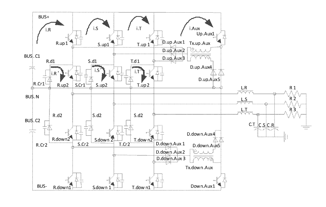
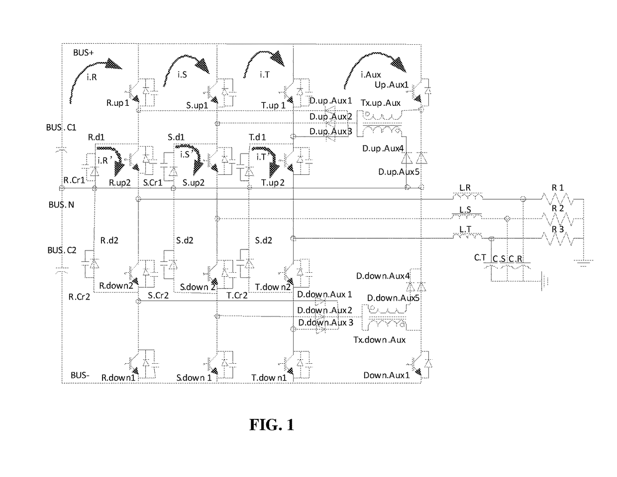
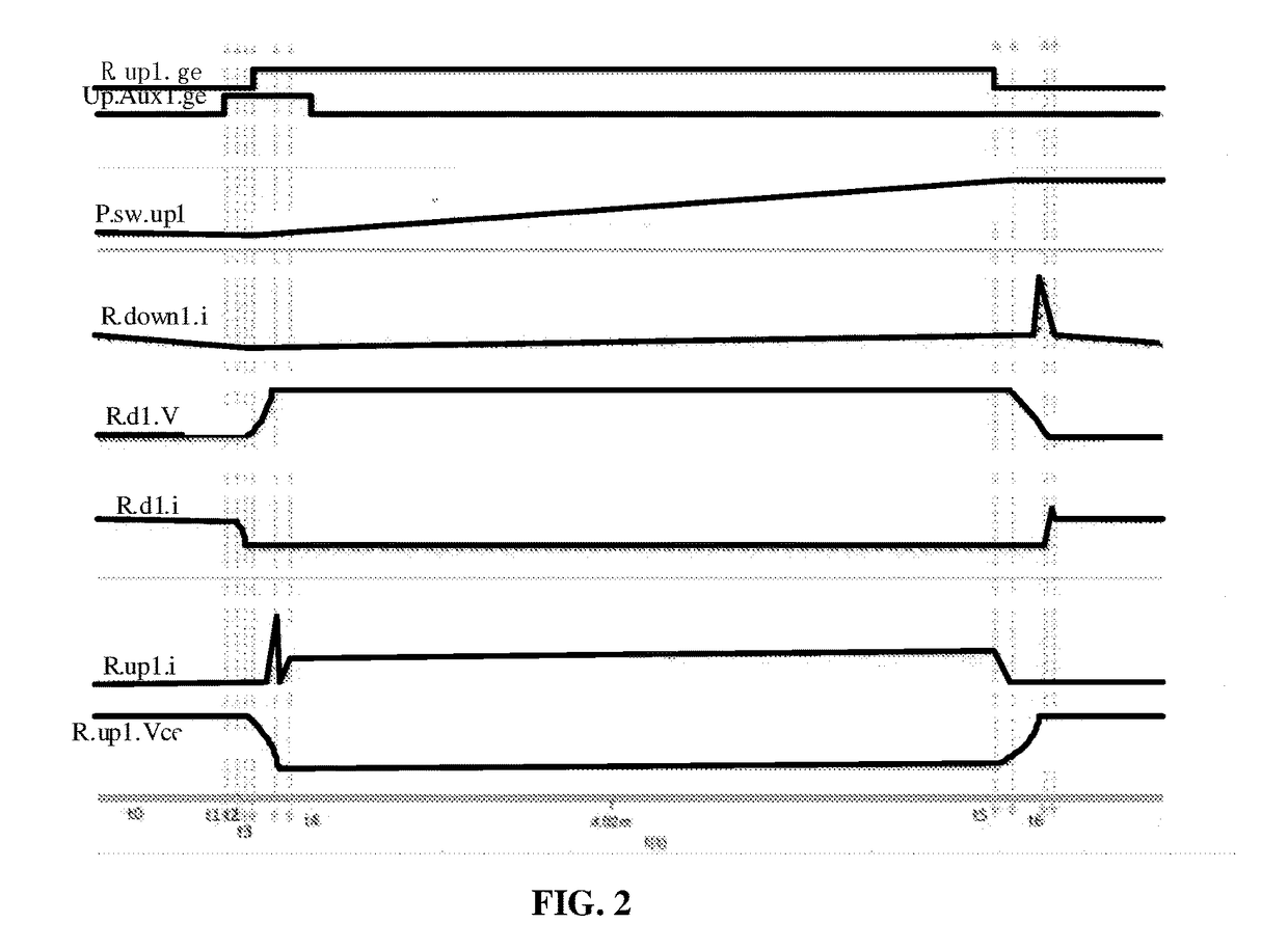
[0054]Referring to FIG. 1 and FIGS. 6a and 6b, and referring to FIG. 2, FIG. 3 and FIG. 4, taking R-phase, S-phase and T-phase output voltages in the positive half cycle as an example, and supposing that a power factor PF=1, a positive bridge arm for each phase operates in a Buck operation mode. Supposing that in the initial state the freewheeling diode R.d1 is on to release magnetism, the auxiliary switch Up.Aux1, the main switch R.up1, the main switch S.up1 and the main switch T.up1 are turned off, then for a R-phase bridge arm, current flows out of the freewheeling diode R.d1, the main switch R.down1 and the inductor L.R to a load R1, and current flow directions of a S-phase bridge arm and a T-phase bridge arm are similar to that of the R-phase bridge arm.

[0055]A control method for a three-phase NPC-type inverter according to one embodiment comprises the steps of:

[0056]S1: detecting whet...


PUM


Abstract

The present invention discloses a control method and device for a circuit with a bridge arm of a switch. The soft switching converter comprises at least two bridge arms of the switch, and an auxiliary switch assisting in switching of a main switch of the bridge arm of the switch. The control method comprises the steps of: S1. after controlling the auxiliary switch to be turned on for a first period of time, controlling main switches set at the same position of individual bridge arms of the switch to be simultaneously turned on; S2. after a second period of time following a time when the main switches set at the same position of individual bridge arms of the switch are simultaneously turned on, turning off the auxiliary switch. The present invention can reduce system loss and noise, so as to improve efficiency.

Description

CROSS REFERENCE TO RELATED APPLICATION[0001]This application claims the priority of Chinese Patent Application No. 201610643264.8, entitled “A CONTROL METHOD AND DEVICE FOR CIRCUIT WITH A BRIDGE ARM OF A SWITCH” filed with the Chinese Patent Office on Aug. 8, 2016, which is incorporated herein by reference in its entirety.TECHNICAL FIELD[0002]The present invention relates to a filed of a circuit, and particularly to a control method and device for a circuit with a bridge arm of a switch.BACKGROUND ART[0003]The development of a power electronic device is orientated to miniaturization, lightweight, high efficiency, and low cost. In the conventional power supply systems, a power semiconductor device is in a hard switching operation state, and there is a larger overlapping area between voltage and current, causing problems such as large switch loss, electromagnetic interference noise, ringing and the like, thus resulting in high cost, huge volume and low efficiency of the systems. If hi...

Claims


Application Information

Patent Timeline
Patent Type & Authority Applications(United States)
IPC IPC(8): H02M1/08H02M1/088H02M7/5387
CPCH02M1/083H02M7/53871H02M1/088H02M2007/4815H02M2001/0058H02M7/219H02M7/5387H02M1/0058H02M7/487Y02B70/10H02M1/0048H02M1/342H02M7/4815
Inventor XU, FUBINHUANG, HAIBING, YANG
Owner EMERSON NETWORK POWER CO LTD
Learn More