Application Method for High-Output LED AC Bulb-Replacement Assembly

Inactive Publication Date: 2018-02-01
SMITH BENNY RAY +1
View PDF1 Cites 0 Cited by
  • Summary
  • Abstract
  • Description
  • Claims
  • Application Information

AI Technical Summary

Benefits of technology

The invention is a way to make it easier to install a high-output LED bulb replacement into various Fresnel lighting instruments. The invention is made up of two separate parts: a part that produces light and a part that connects to the electrical power. This two-part design allows for bigger and brighter LED bulbs to be installed easily into the instrument. It takes just two screws to join the two parts once they are inside the instrument. Overall, this invention simplifies the process of replacing LED bulbs in Fresnel lighting instruments.

Problems solved by technology

The power consumption of these instruments ranges from hundreds to thousands of watts.

Method used


Image

  • Application Method for High-Output LED AC Bulb-Replacement Assembly
  • Application Method for High-Output LED AC Bulb-Replacement Assembly
  • Application Method for High-Output LED AC Bulb-Replacement Assembly

Examples


Embodiment Construction

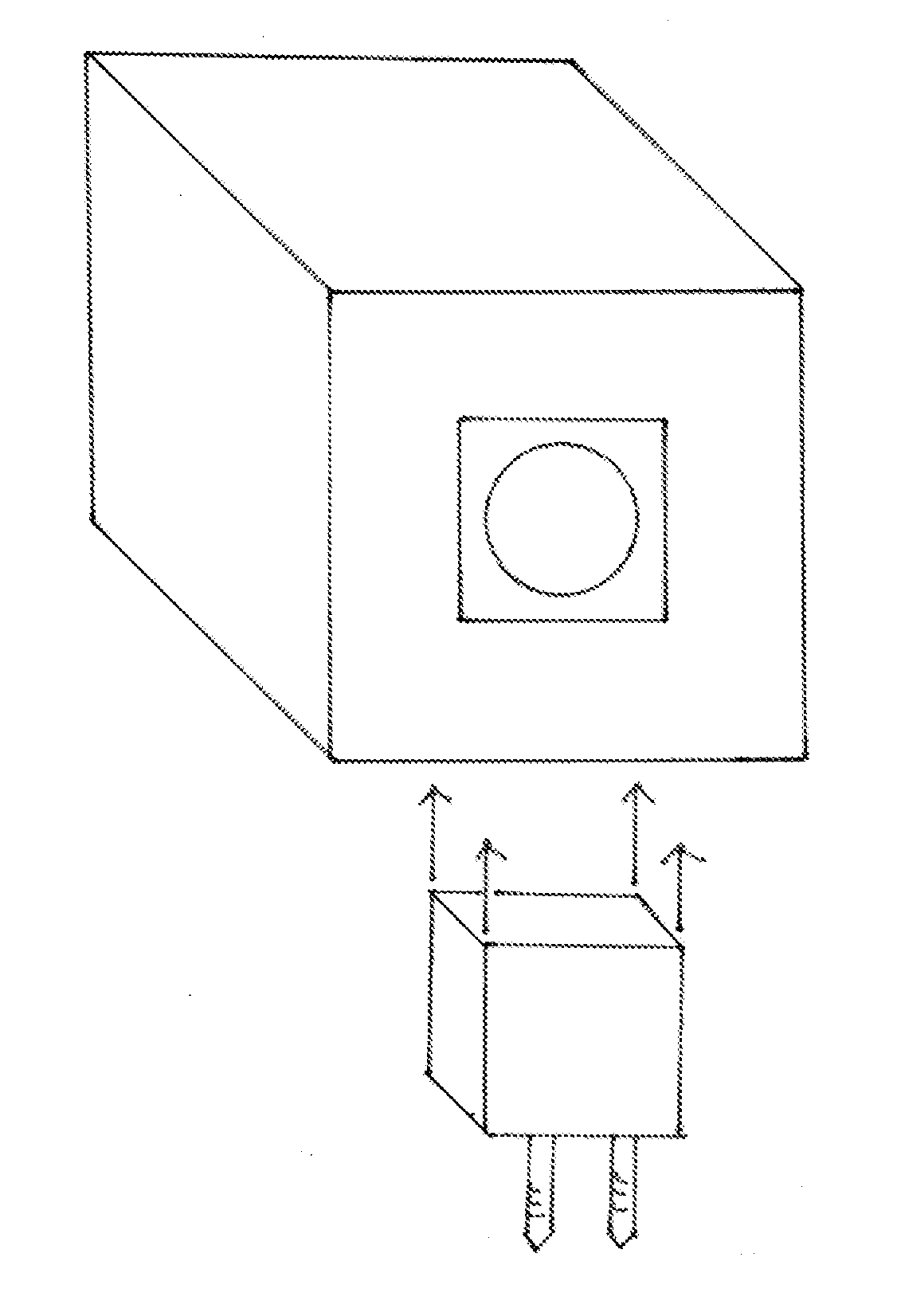
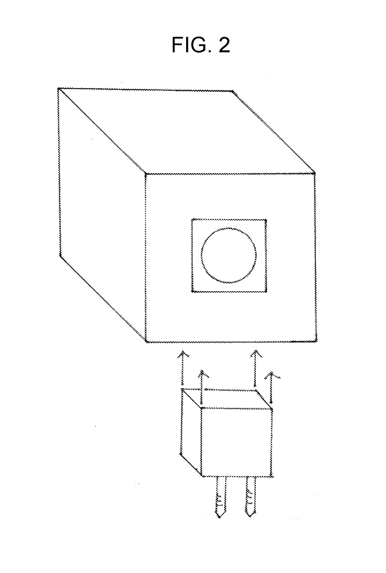
[0021]The invention consists of the separation of a high-output LED bulb-replacement assembly into two distinct parts: a light-producing sub-assembly and an electrical-power-contact sub-assembly.

[0022]These two parts complement one another. Their separation allows a high-output LED bulb-replacement assembly to be installed into spaces where, fully assembled, it could not be inserted.

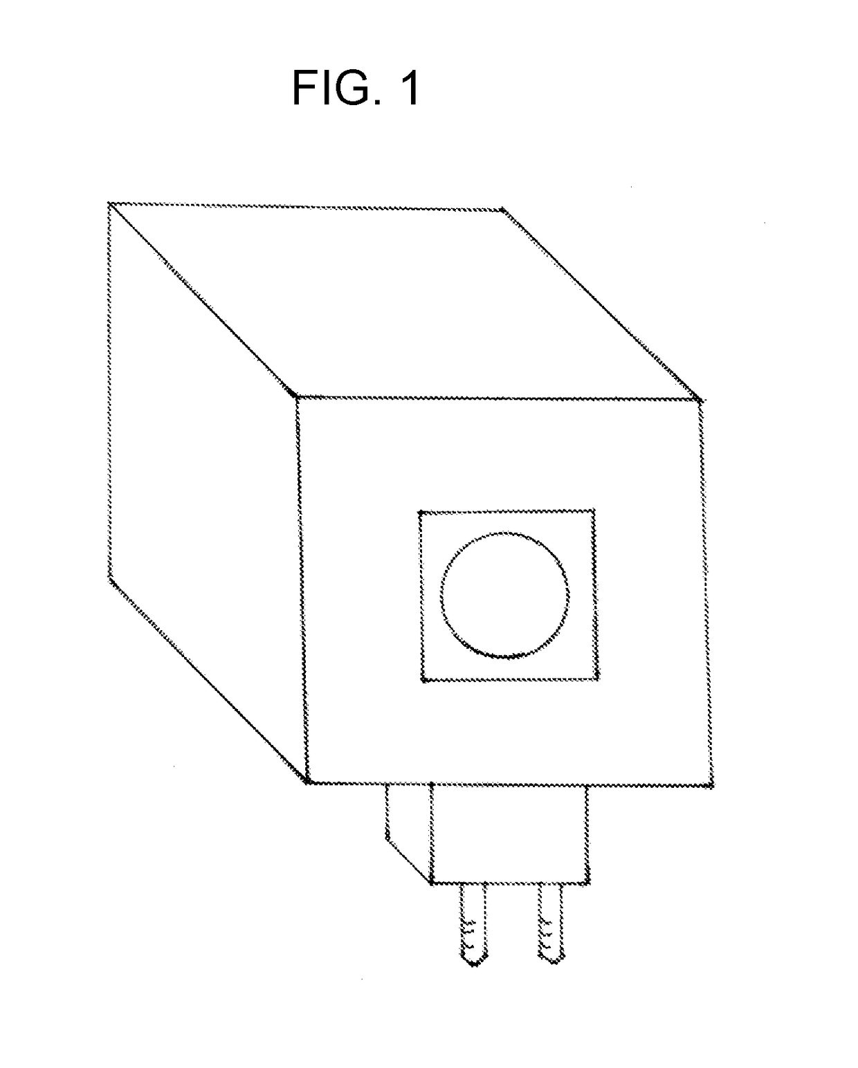
[0023]The light-producing sub-assembly and the electrical-power-contact sub-assembly can each take various forms. A complete high-output LED bulb-replacement assembly is depicted in FIG. 1, with the light-producing assembly shown as (10), the LED emitter shown as (12) and the electrical-power-contact sub-assembly shown as (14). FIG. 2 shows an exploded view of the constituent sub-assemblies, wherein the light-producing assembly is shown as (16), the electrical-power-contact sub-assembly is shown as (18) and the AC contact pins are shown as (20).


PUM


Abstract

A means for facilitating the installation of a high-output LED bulb-replacement assembly into various Fresnel lighting instruments. The invention consists of partitioning the bulb-replacement assembly into two distinct parts: a light-producing sub-assembly and an electrical-power-contact sub-assembly. This partition greatly simplifies the application of the high-output LED bulb replacement assembly to a wide variety of existing Fresnel instruments.

Description

CROSS-REFERENCES TO RELATED APPLICATIONS[0001]NoneSTATEMENT REGARDING FEDERALLY-SPONSORED RESEARCH OR DEVELOPMENT[0002]Not ApplicableMICROFICHE APPENDIX[0003]Not ApplicableBACKGROUND OF THE INVENTION1. Field of the Invention[0004]The invention comprises an application extension of the previous invention of a “High-Output LED AC Bulb-Replacement Assembly”2. Description of the Related Art[0005]In a previous patent application by the same persons as above, “High-Output LED AC Bulb Replacement Assembly”, a design for a single-assembly, direct, plug-in replacement for the halogen bulb used in existing lighting instruments was described. In order to provide continuity to the present invention, the background art described in that patent is repeated.[0006]The lighting instruments that have been in use for decades employ halogen light bulbs as their light source. The power consumption of these instruments ranges from hundreds to thousands of watts. Typically, 93% or more of this power is co...

Claims


Application Information

Patent Timeline
IPC IPC(8): F21K9/235F21V5/04F21K9/232
CPCF21K9/235F21K9/232F21V5/045F21Y2115/10F21K9/23
Inventor SMITH, BENNY RAYSMITH, PETER ANDREW
Owner SMITH BENNY RAY
Why Eureka
Try Eureka