Spark plug

a technology of spark plugs and electrode tips, which is applied in the field of spark plugs, can solve the problems of insufficient studies on the application of the above-described material and the difficulty of sufficiently ensuring and achieve the effect of improving the separation resistance of the electrode tip

Active Publication Date: 2018-01-18
NGK SPARK PLUG CO LTD
View PDF0 Cites 0 Cited by
  • Summary
  • Abstract
  • Description
  • Claims
  • Application Information

AI Technical Summary

Benefits of technology

[0007]The present description discloses, in a spark plug that includes an electrode tip having a cover layer formed of an IrAl intermetallic compound, a technology for improving separation resistance of the electrode tip.
[0010]With this structure, the tip body and the electrode body can be bonded to each other by the welded portion on a sufficiently large area. As a result, in the spark plug that includes an electrode tip having a cover layer formed of an IrAl intermetallic compound, separation resistance of the electrode tip can be improved.Application Example 2
[0014]With this structure, the tip body and the electrode body can be bonded to each other on a sufficiently large area with respect to the area Sc of a portion of the electrode tip, the portion receiving heat. As a result, in the spark plug that includes an electrode tip having a cover layer formed of an IrAl intermetallic compound, separation resistance of the electrode tip can be further improved.Application Example 4
[0018]This structure further suppresses a phenomenon that the welded portion is unlikely to deform and becomes brittle in the vicinity of the boundary between the tip body and the welded portion. Thus, separation resistance of the electrode tip can be particularly improved.

Problems solved by technology

There have not been sufficient studies on applications of the above-described material to an electrode tip of a spark plug.
In particular, there have not been sufficient studies on bonding of an electrode tip formed by using the material and an electrode body to each other, and thus it may be difficult to sufficiently ensure separation resistance of the electrode tip.

Method used


Image

  • Spark plug
  • Spark plug
  • Spark plug

Examples


first embodiment

A. First Embodiment

[0030]A-1. Structure of Spark Plug

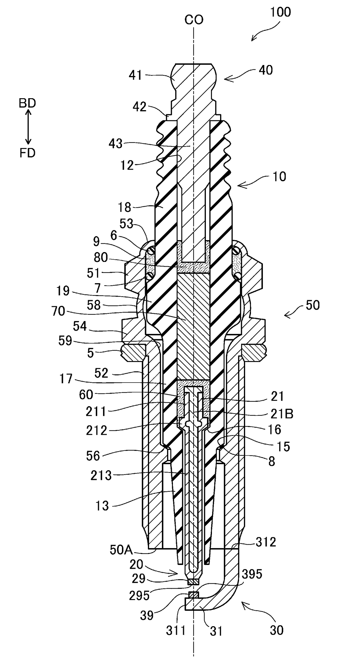
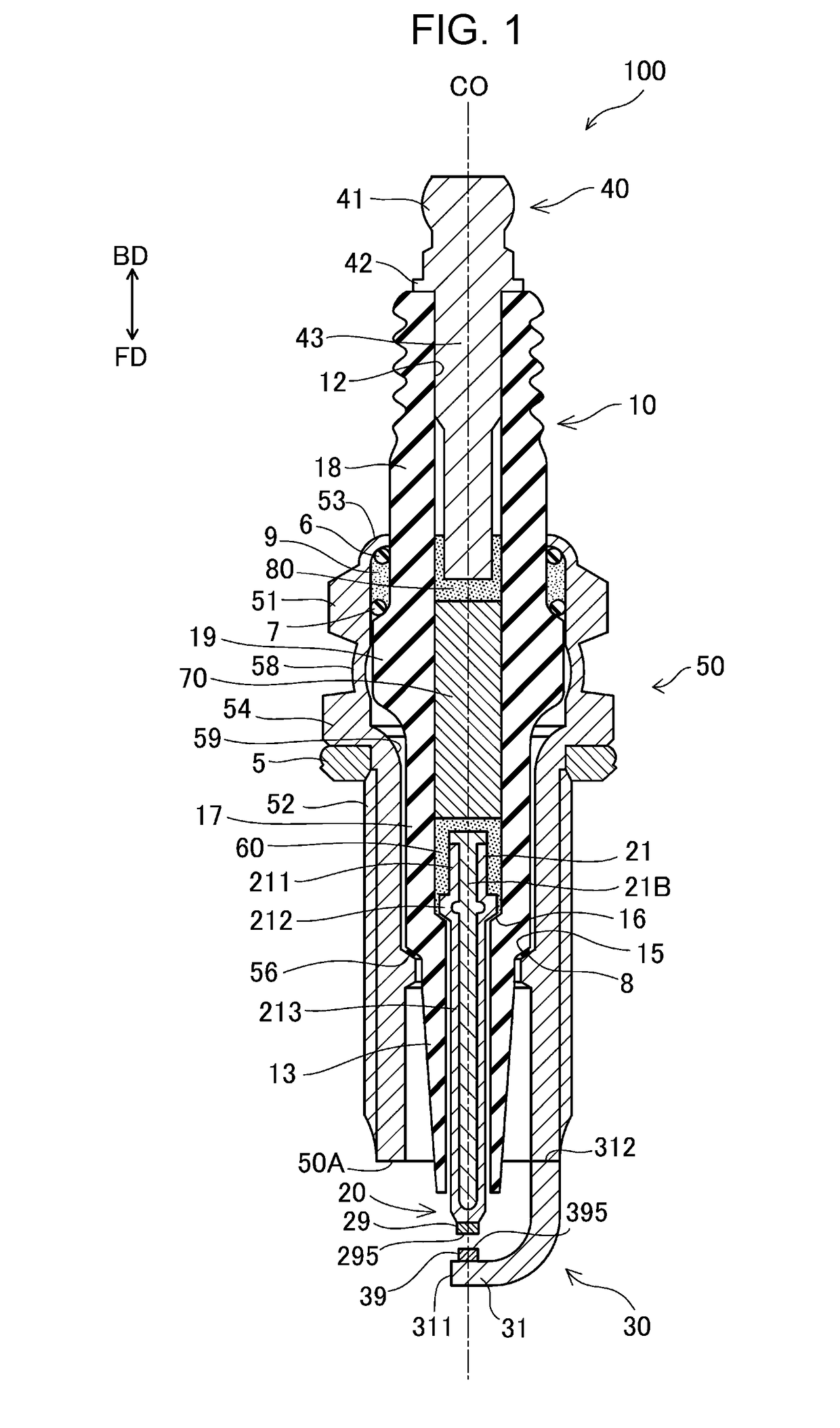
[0031]FIG. 1 is a sectional view of a spark plug 100 according to an embodiment. The one-dotted chain line in FIG. 1 indicates an axial line CO of the spark plug 100. A direction parallel to the axial line CO (up-down direction in FIG. 1) may be referred to as an “axial line direction”. A radial direction of a circle centered at the axial line CO may be simply referred to as a “radial direction”. A circumferential direction of a circle centered at the axial line CO may be simply referred to as a “circumferential direction”. The down direction in FIG. 1 may be referred to as a “forward direction FD”, and the up direction in FIG. 1 may be referred to as a “backward direction BD”. The lower side in FIG. 1 is referred to as a “front side” of the spark plug 100, and the upper side in FIG. 1 is referred to as a “back side” of the spark plug 100. The spark plug 100 includes an insulator 10 serving as an insulator, a center electrode 20, ...

second embodiment

B. Second Embodiment

[0073]FIGS. 6A and 6B are views illustrating a structure around a front end of a center electrode of a second embodiment. FIG. 6A is a sectional view of a portion around a front end of a center electrode taken along a plane including an axial line CO. In the second embodiment, a center electrode tip 29b is used instead of the center electrode tip 29 of the first embodiment. In this center electrode tip 29b, a side surface 273b of a tip body 27b, a surface (front surface) 275b on the first discharge surface 295b side, and an opposite surface 271b disposed on the opposite side of the first discharge surface 295b are covered with a cover layer 28b. Therefore, in the second embodiment, in addition to the side surface 293b of the center electrode tip 29b, the first discharge surface 295b is also formed by the cover layer 28b. This center electrode tip 29b can be prepared by forming an IrAl intermetallic compound film, by the aluminizing process, on a base prepared in ...

third embodiment

C. Third Embodiment

[0078]FIG. 7 illustrates a sectional view of a portion around a front end of a center electrode of a third embodiment taken along a plane including an axial line CO. Unlike the first embodiment, since the welding depth D in the third embodiment is sufficiently large, a welded portion 25c reaches a position intersecting the axial line CO. Therefore, the welded portion 25c has, for example, a substantially columnar shape. The entire opposite surface 271 of a center electrode tip 29 forms a contact portion that is in contact with the welded portion 25c, and a non-contact portion that is not in contact with the welded portion 25c is not present. Other structures are the same as those of the first embodiment.

[0079]In the third embodiment, since a non-contact portion is not present, a projection image to be projected on a particular section CFc is also not present. Therefore, in the third embodiment, the area Sb of the projection image of the non-contact portion is zero...


PUM


Abstract

At least one of a center electrode and a ground electrode of a spark plug includes an electrode body, an electrode tip, and a welded portion formed between the electrode body and the electrode tip. The electrode tip includes a cover layer that covers at least a side surface of a tip body, and the cover layer is formed of IrAl. On a section formed by cutting the electrode tip near a boundary with the welded portion, an area of the tip body is represented by Sa. An area of a projection on the section of a non-contact portion of an opposite surface of the tip body not in contact with the welded portion is represented by Sb. In this case, Sa−Sb corresponds to 35% or more of Sa.

Description

CROSS REFERENCE TO RELATED APPLICATION[0001]The present application claims priority to Japanese Patent Application No. 2016-138603, filed Jul. 13, 2016, and Japanese Patent Application No. 2017-097916 filed May 17, 2017, the entire disclosures of which are hereby incorporated herein by reference.BACKGROUND OF THE INVENTIONField of the Invention[0002]The present description relates to a spark plug for causing fuel gas to ignite in an internal combustion engine or the like.Description of the Related Art[0003]Spark plugs used in internal combustion engines cause, for example, spark discharge in a gap formed between a center electrode and a ground electrode to cause fuel gas to ignite in an internal combustion engine or the like. A spark plug is known in which, in order to improve wear resistance, an electrode tip formed of a noble metal such as iridium is bonded to a portion of a center electrode or a ground electrode, the portion forming a gap where spark discharge occurs.[0004]Patent...

Claims


Application Information

Patent Timeline
Patent Type & Authority Applications(United States)
IPC IPC(8): H01T13/39H01T13/10H01T13/32H01T13/38
CPCH01T13/39H01T13/38H01T13/10H01T13/32H01T13/20
Inventor SUMOYAMA, DAISUKENAKADA, TAKUTOSHIBATA, TSUTOMUKIKAI, TAKAAKI
Owner NGK SPARK PLUG CO LTD
Why Eureka
Try Eureka