
Method for producing multi-core optical fiber

Inactive Publication Date: 2018-01-18
SUMITOMO ELECTRIC IND LTD
View PDF3 Cites 0 Cited by
  • Summary
  • Abstract
  • Description
  • Claims
  • Application Information

AI Technical Summary

Benefits of technology

The present invention provides a method for producing a multi-core optical fiber that includes a plurality of cores made of pure silica glass and exhibits a minor transmission loss. This allows for the production of a more efficient and cost-effective optical fiber with improved performance.

Problems solved by technology

It is known that the residual stress in the core may cause the pure silica core optical fiber to undergo a change in refractive index profile or to exhibit glass defects that cause an increase in transmission loss (see Y. Hibino et al.
However, an excessively low drawing tension increases the likelihood that the optical fiber vibrates between the neck down portion and a take-up roller and shows a variation in fiber diameter and core diameter in the longitudinal direction.
A slight variation in core diameter may result in an increase in transmission loss.

Method used


Image

  • Method for producing multi-core optical fiber
  • Method for producing multi-core optical fiber
  • Method for producing multi-core optical fiber

Examples


example 2

In Example 2, the outer glass diameter of an optical fiber was 140 μm, the average core diameter was 8 μm, and the number of cores N was 4.

[0031]Table 3 shows production conditions, etc. of multi-core optical fibers of Example 3.

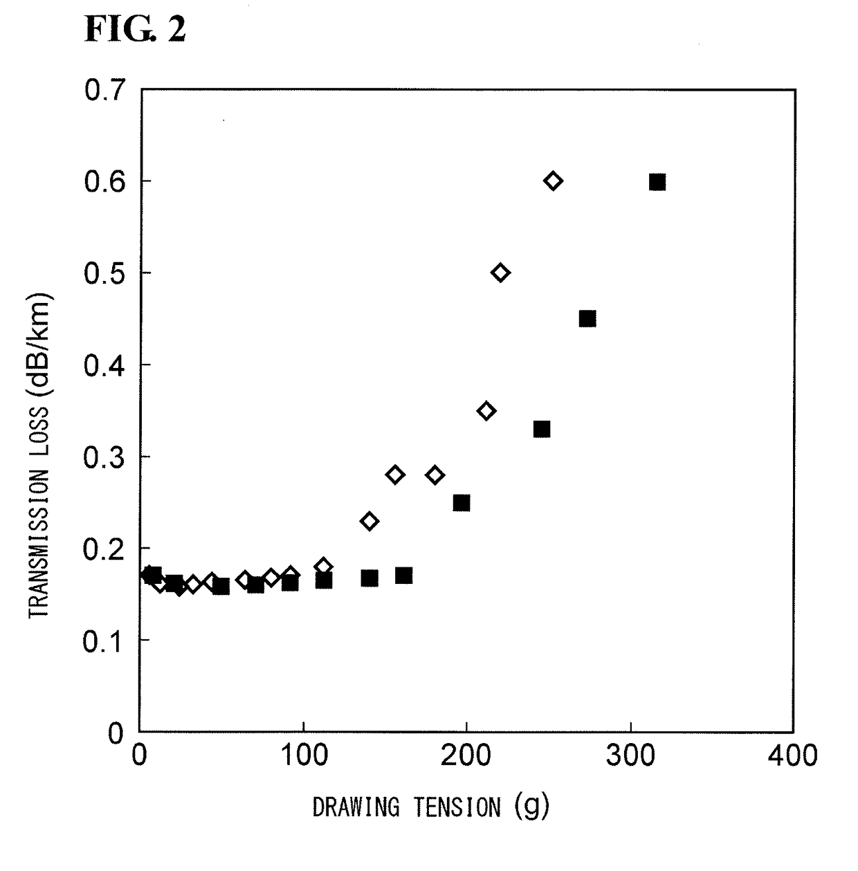
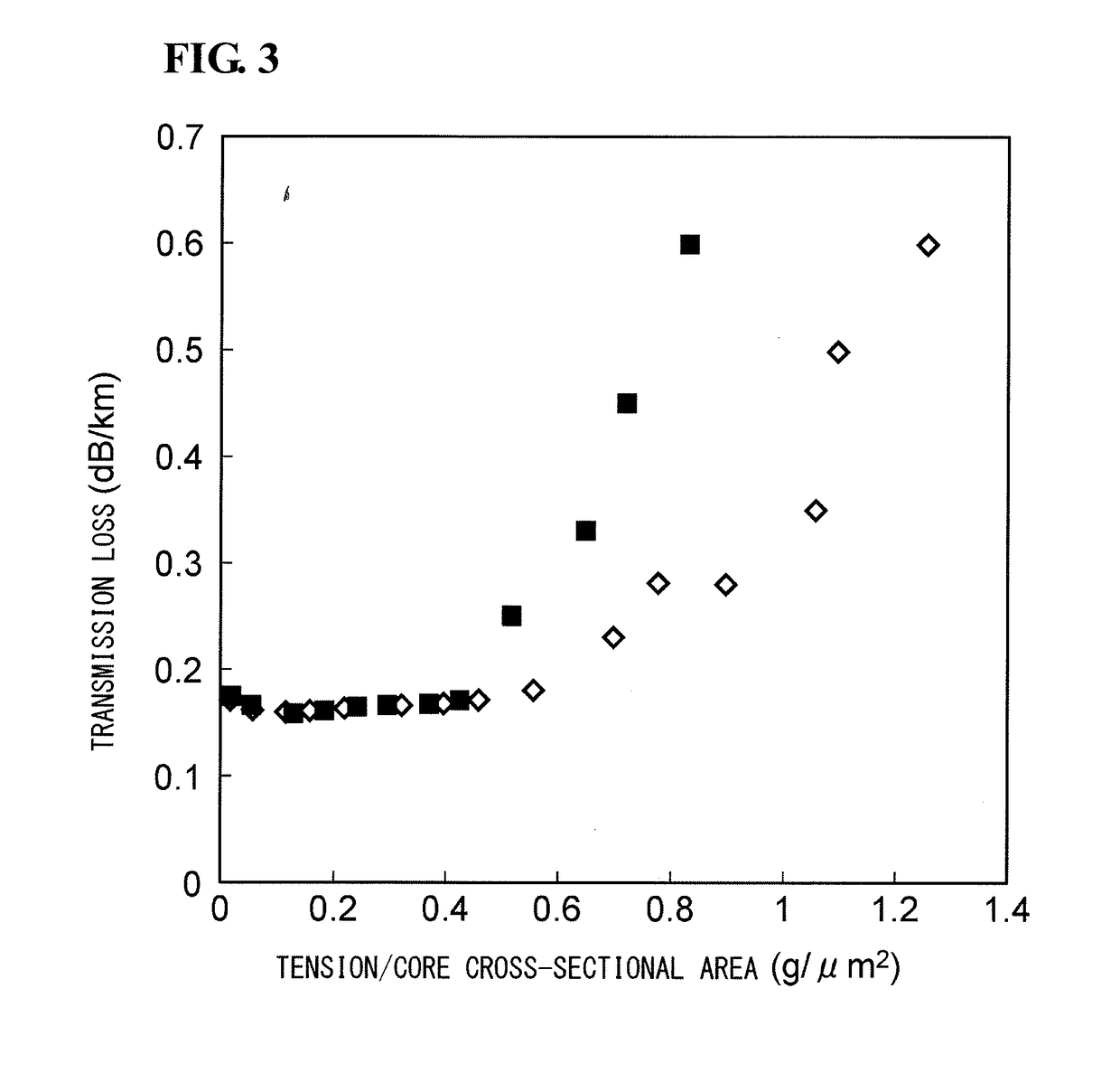
TABLE 3Tension percore cross-DrawingTensionsectionalTransmissiontensionper corearea T / ST / (S / Sf)lossT (g)T / N (g)(g / μm2)(g)(dB / km)720.024690.1732150.0614060.16549120.1332800.15870180.1846860.16191230.2460920.164112280.2974980.165140350.3793720.167161400.42107780.17196490.52131210.25245610.64164010.33273680.72182750.45315790.83210870.6

example 3

In Example 3, the outer glass diameter of an optical fiber was 180 μm, the average core diameter was 11 μm, and the number of cores N was 4.

[0032]Table 4 shows production conditions, etc. of single-core optical fibers of Comparative Example.

TABLE 4Tension percore cross-DrawingTensionsectionalTransmissiontensionper corearea T / ST / (S / Sf)lossT (g)T / N (g)(g / μm2)(g)(dB / km)110.022440.18330.067320.175660.1214650.158880.1619530.1611110.2226860.16216160.3239060.16320200.4048830.15825250.5061040.15431310.6275680.1535350.7085450.1539390.7895210.15445450.90109860.15853531.05129390.1655551.09134280.1763631.25153810.1866661.31161130.19174741.47180660.2583831.65202640.4

In Comparative Example, the outer glass diameter of an optical fiber was 125 μm, the average core diameter was 8 μm, and the number of cores N was 1.

[0033]FIG. 2 is a graph showing the relationship between drawing tension T and transmission loss. FIG. 3 is a graph showing the relationship between tension per core cross-sectional area...


PUM

PropertyMeasurementUnit
Pressureaaaaaaaaaa
Massaaaaaaaaaa
Massaaaaaaaaaa

Abstract

Provided is a method for producing a multi-core optical fiber that includes a plurality of cores made of pure silica glass and exhibits a minor transmission loss. The method for producing a multi-core optical fiber according to the present invention is a method for producing a multi-core optical fiber including a plurality of cores made of pure silica glass substantially free of Ge and a cladding surrounding the plurality of cores and made of a fluorine-containing silica glass. The multi-core optical fiber is produced by drawing an optical fiber preform at a drawing tension T satisfying the relationship 0.06 g / μm2<T / S<0.4 g / μm2, wherein S is a total cross-sectional area of the plurality of cores.

Description

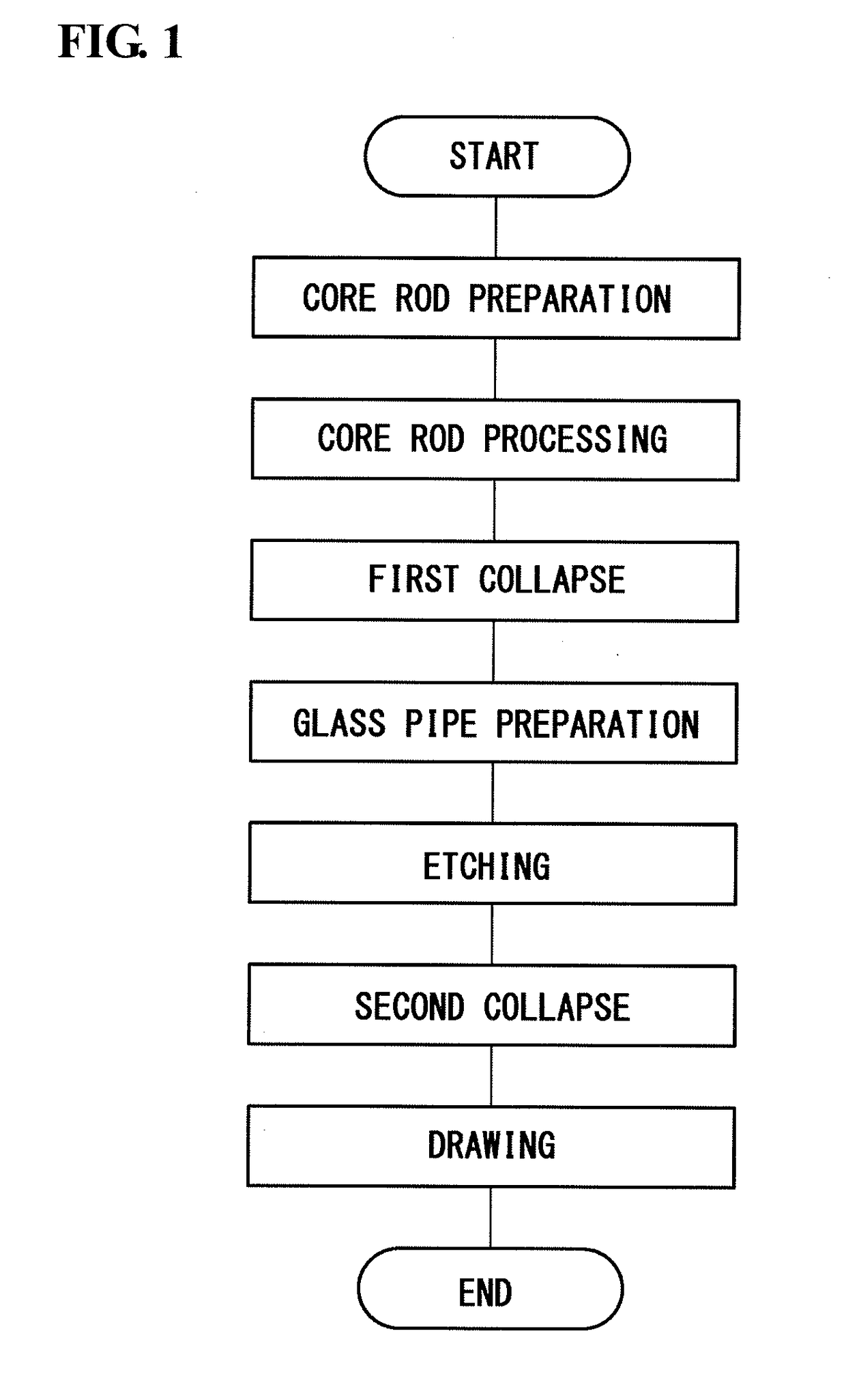
BACKGROUND OF THE INVENTIONField of the Invention[0001]The present invention relates to a method for producing a multi-core optical fiber.Description of the Related Art[0002]A pure silica core optical fiber includes a core made of pure silica glass substantially free of Ge and a cladding surrounding the core and made of a fluorine-containing silica glass. In general, pure silica core optical fibers experience low Rayleigh scattering in the core and thus exhibit a transmission loss smaller than those of optical fibers including a core made of a Ge-containing silica glass.[0003]When a pure silica core optical fiber is produced by drawing an optical fiber preform, a drawing tension is concentrated in the core because the viscosity of the core is higher than the viscosity of the cladding, and as a result, a residual stress occurs in the core. It is known that the residual stress in the core may cause the pure silica core optical fiber to undergo a change in refractive index profile or t...

Claims


Application Information

Patent Timeline
IPC IPC(8): C03B37/025C03B37/027G02B6/02
CPCC03B37/0253C03B2205/40C03B37/027G02B6/02042C03B2201/075C03B2201/12C03B2203/34C03C2201/12C03C2201/23C03B37/01222C03C3/06C03C13/045C03C25/68C03C25/70C03C2201/02
Inventor TAMURA, YOSHIAKIHASEGAWA, TAKEMI
Owner SUMITOMO ELECTRIC IND LTD
Learn More