
Adjustable Wrench

a wrench and adjustment technology, applied in the field of hand tools, can solve the problems of poor stability of the transmission mechanism of itself, poor practicability of the thumb wheel operation, poor stability of the thumb wheel, etc., and achieve the effects of convenient operation, high stability, and rapid adjustmen

Active Publication Date: 2018-01-18
HANGZHOU GREAT STAR TOOLS +1
View PDF2 Cites 8 Cited by
  • Summary
  • Abstract
  • Description
  • Claims
  • Application Information

AI Technical Summary

Benefits of technology

The patent text describes a problem in the prior art where adjustable wrenches were unstable and difficult to operate. The invention provides a new adjustable wrench with high stability that allows for easy and convenient adjustment of the jaws. The jaws can be tightly connected to the workpiece, and the wrench operates with rapid adjustment, high stability, and self-lock function to prevent the jaws from coming loose during rotation.

Problems solved by technology

Various hand tools of various different types are often prepared due to different models and types of workpieces, which is very inconvenient.
While this adjustable ratchet wrench realizes the adjustment function for jaws, it has very poor practicability.
Firstly, the operation of the thumb wheel is not convenient, secondly, the stability of the transmission mechanism of itself is poor, and thirdly, the pair of jaws adjusted by the gear shaft is not secured in use.

Method used


Image

  • Adjustable Wrench
  • Adjustable Wrench
  • Adjustable Wrench

Examples


embodiment 1

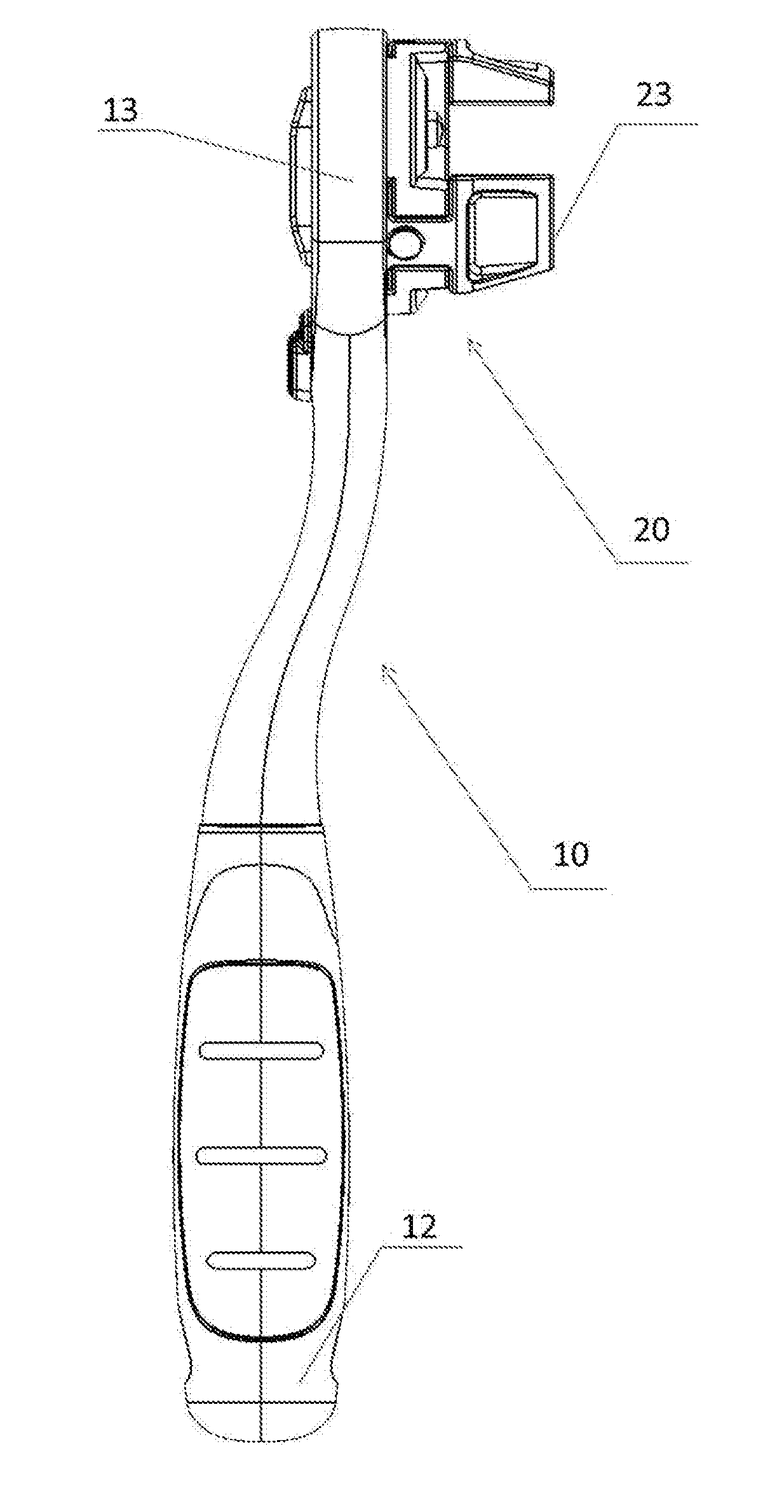
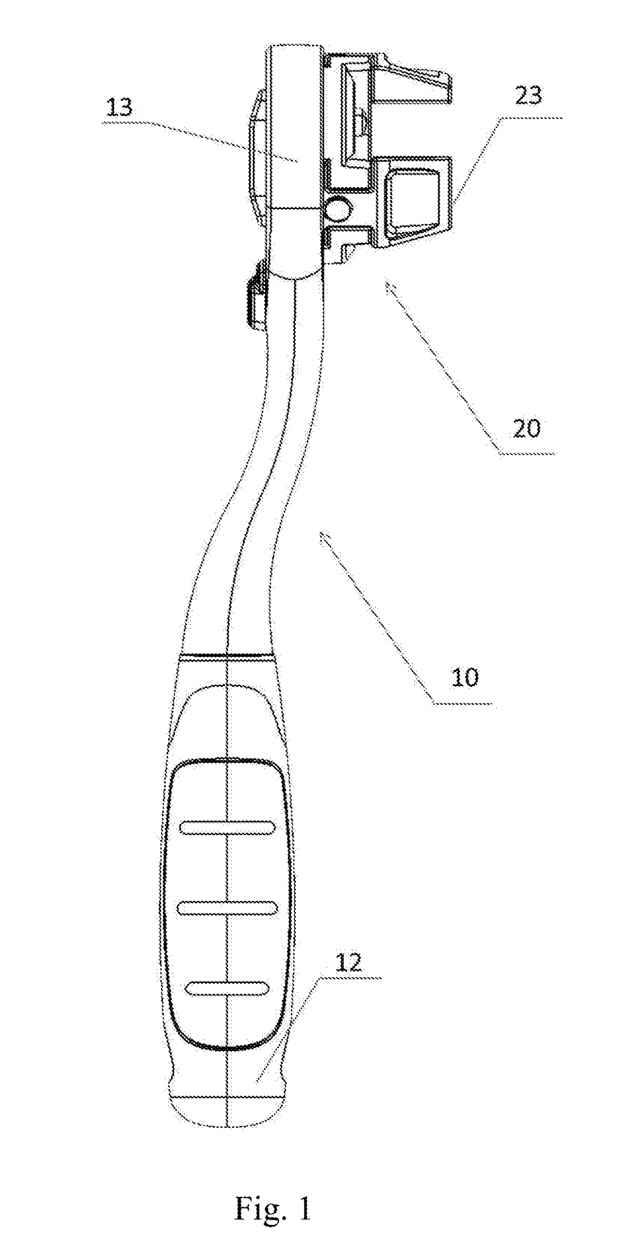
[0040]As shown in FIG. 1, the adjustable wrench of the present invention includes a handle 10 and a working portion 20. The handle 10 has a first end 12 and a second end 13 opposite the first end 12. The second end 13 has a head portion 11 (see FIG. 2) and is connected to the working portion 20. Jaws 23 are provided on the working portion and are adapted for operation of various types of workpieces by being configured into different shapes. The adjustable wrench of the present invention may have two or more jaws. Preferably, there are three jaws in this embodiment, which are distributed along the circumferential direction of the working portion 20.

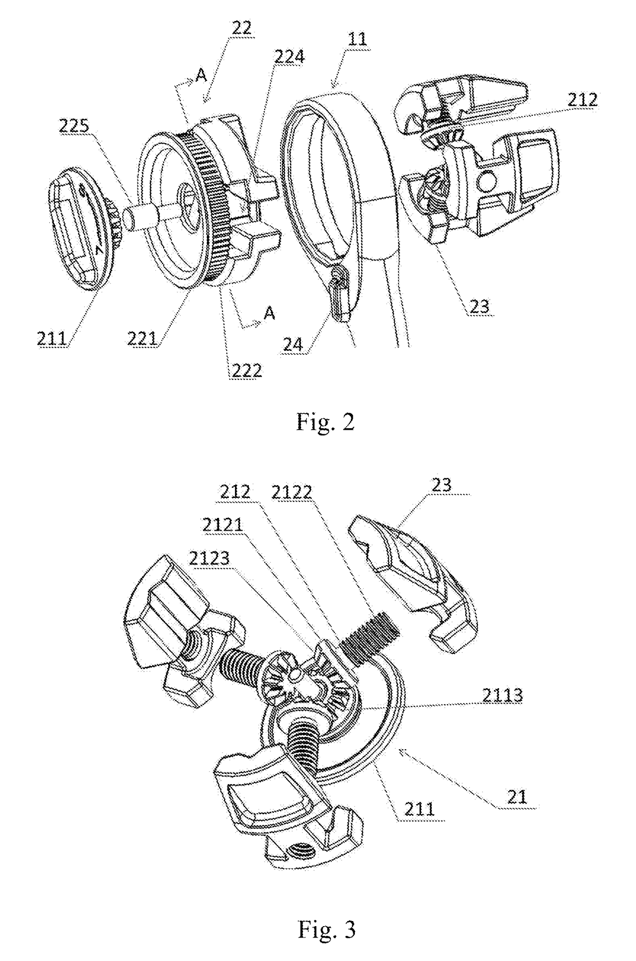
[0041]The structure of the working portion 20 of the adjustable wrench in this embodiment is as shown in FIGS. 2 and 3, which includes a base 22, jaws 23, a reversing device 24 and an adjusting device 21. The head portion 11 of the handle 10 are connected to the base 22, in which the base 22 is selectively actuated to rotate in a first dir...

embodiment 2

[0047]As the adjustable wrench in Embodiment 1, in this embodiment, the structure of the working portion 20 of the adjustable wrench is as shown in FIG. 9, which includes a base 22, jaws 23, a reversing device 24 and a knob 211, in which the base 22 includes a first rotary member 221 and a second rotary member 222. The first rotary member 221 and the second rotary member 222 have a outer toothed surface and an inner toothed surface that are fitted with each other, respectively, so that the first rotary member 221 can actuate the second rotary member 222 to rotate about its axis. The head portion 11 of the handle 10 is connected to the base 22, in which the base 22 is selectively actuated to rotate in a first direction or a second direction about its axis by the reversing device 24 and in the other direction slipping occurs, in which the first direction is clockwise direction or counterclockwise direction, the second direction being opposed to the first direction. A groove portion 22...


PUM


Abstract

Disclosed is an adjustable wrench including a handle and a working portion. The working portion includes an adjusting device and at least two jaws. The jaws are distributed along the circumferential direction of the working portion, and the adjusting device is arranged such as to adjust the jaws to simultaneously move in a radial direction of the working portion, closer to or away from the center of the working portion, that is, the jaw opening defined by the plurality of jaws are adjustable. The adjustable wrench provided by the invention is adapted for workpieces of various specifications, and can realize rapid adjustment.

Description

FIELD OF THE INVENTION[0001]The invention relates to a hand tool, and more particularly to an adjustable wrench.DESCRIPTION OF THE PRIOR ART[0002]A hand tool such as a wrench generally includes a handle and jaws that are fixedly mounted to the handle. The jaws may extend along the direction of the handle or along the direction perpendicular to the handle. A plurality of jaws may form a jaw opening fitting with a workpiece. In practice, one often needs to deal with workpieces of different specifications and types, and only the wrenches of the corresponding type can be used stably and efficiently to fit with the workpiece. If the jaw opening of the wrench does not fit with a workpiece, the wrench cannot be used or would come loose in use, so usually a wrench of a corresponding type needs to be selected according to the specific dimensions of a workpiece. Various hand tools of various different types are often prepared due to different models and types of workpieces, which is very inco...

Claims


Application Information

Patent Timeline
IPC IPC(8): B25B13/14B25B13/46
CPCB25B13/14B25B13/46
Inventor WANG, MIN
Owner HANGZHOU GREAT STAR TOOLS
Learn More