
Led-based illumination assembly with adjustable irradiation angle

an illumination assembly and led-based technology, applied in the direction of lighting and heating apparatus, semiconductor devices for light sources, lighting support devices, etc., can solve the problems of environmental pollution during disposal, large energy consumption, rapid reduction of light amount, etc., to prevent the occurrence of costs, reduce energy consumption, and reduce power consumption

Active Publication Date: 2018-01-11
SAEVIT ELECTRIC & LIGHTING CO LTD
View PDF3 Cites 9 Cited by
  • Summary
  • Abstract
  • Description
  • Claims
  • Application Information

AI Technical Summary

Benefits of technology

The present invention is about an LED-based illumination assembly with adjustable irradiation angle. This allows for simple and precise adjustment of the angle of light irradiation without the need for expensive lenses with different angles. The invention reduces costs and improves reliability while also promoting energy savings. Additionally, this allows for flexibility in installation height and usage purpose, enhancing the versatility of the LED-based illumination modules.

Problems solved by technology

In this case, there is a problem that the energy consumption is larger relative to the brightness, and the light amount is rapidly lowered with time due to the short life time.
Particularly, since mercury lamps use mercury gas, they have a problem of causing environmental pollution during disposal.
Therefore, the irradiation area is narrow, and various lighting devices using the LED lamp have a limited uniform illuminance and a limited light distribution area.
This increases the cost of the lens mold (in fact, the lens mold requires a high level of technology and is expensive), and the costs of the lens itself and the stockpile thereof incur, resulting in a high production cost.
This requires a high level of expertise, resulting in labor costs.
In the case of a lighting device with several LED-based illumination modules, the amount of light for each of the LED-based illumination modules cannot be adjusted arbitrarily.
However, for example, when a lighting device is installed close to a wall, the light emitted from the LED-based illumination modules thereof in a position cannot be directed to a location far away from the wall.
There is a problem that energy cannot be saved.
However, this document does not disclose a configuration in which, in a lighting apparatus including several light sources, the light irradiation angle for each light source is individually adjusted.
Therefore, the amount of light cannot be reasonably adjusted depending on the installation place, situation, purpose, etc. of the lighting equipment.
Also, energy savings cannot be achieved.
Further, the structure for installing the angle adjusting means between the main body and the bracket is very complicated.
This causes a problem that the production cost of the product itself increases due to unnecessary mold production cost.
Therefore, the production cost is increased unnecessarily, and the failure rate is increased.
In particular, the light irradiation angles for a plurality of light emitting units cannot be individually adjusted.
Therefore, the amount of light cannot be reasonably adjusted in accordance with the installation place and situation of the lighting apparatus.
In addition, there is a problem that energy cannot be saved.
Therefore, the production cost is high, and the configuration of the irradiation angle adjustment mechanism is complicated.
As a result, the weight of the lighting apparatus itself is increased, the manufacturing cost is increased, and the assembling time is long.

Method used


Image

  • Led-based illumination assembly with adjustable irradiation angle
  • Led-based illumination assembly with adjustable irradiation angle
  • Led-based illumination assembly with adjustable irradiation angle

Examples


Embodiment Construction

[0049]Examples of various embodiments are illustrated and described further below. It will be understood that the description herein is not intended to limit the claims to the specific embodiments described. On the contrary, it is intended to cover plate alternatives, modifications, and equivalents as may be included within the spirit and scope of the present disclosure as defined by the appended claims.

[0050]It will be understood that, although the terms “first”, “second”, “third”, and so on may be used herein to describe various elements, components, regions, layers and / or sections, these elements, components, regions, layers and / or sections should not be limited by these terms. These terms are used to distinguish one element, component, region, layer or section from another element, component, region, layer or section. Thus, a first element, component, region, layer or section described below could be termed a second element, component, region, layer or section, without departing...


PUM


Abstract

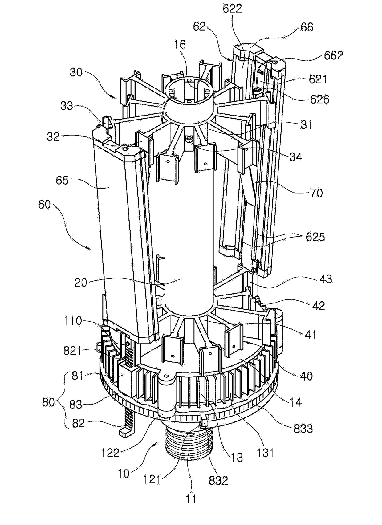
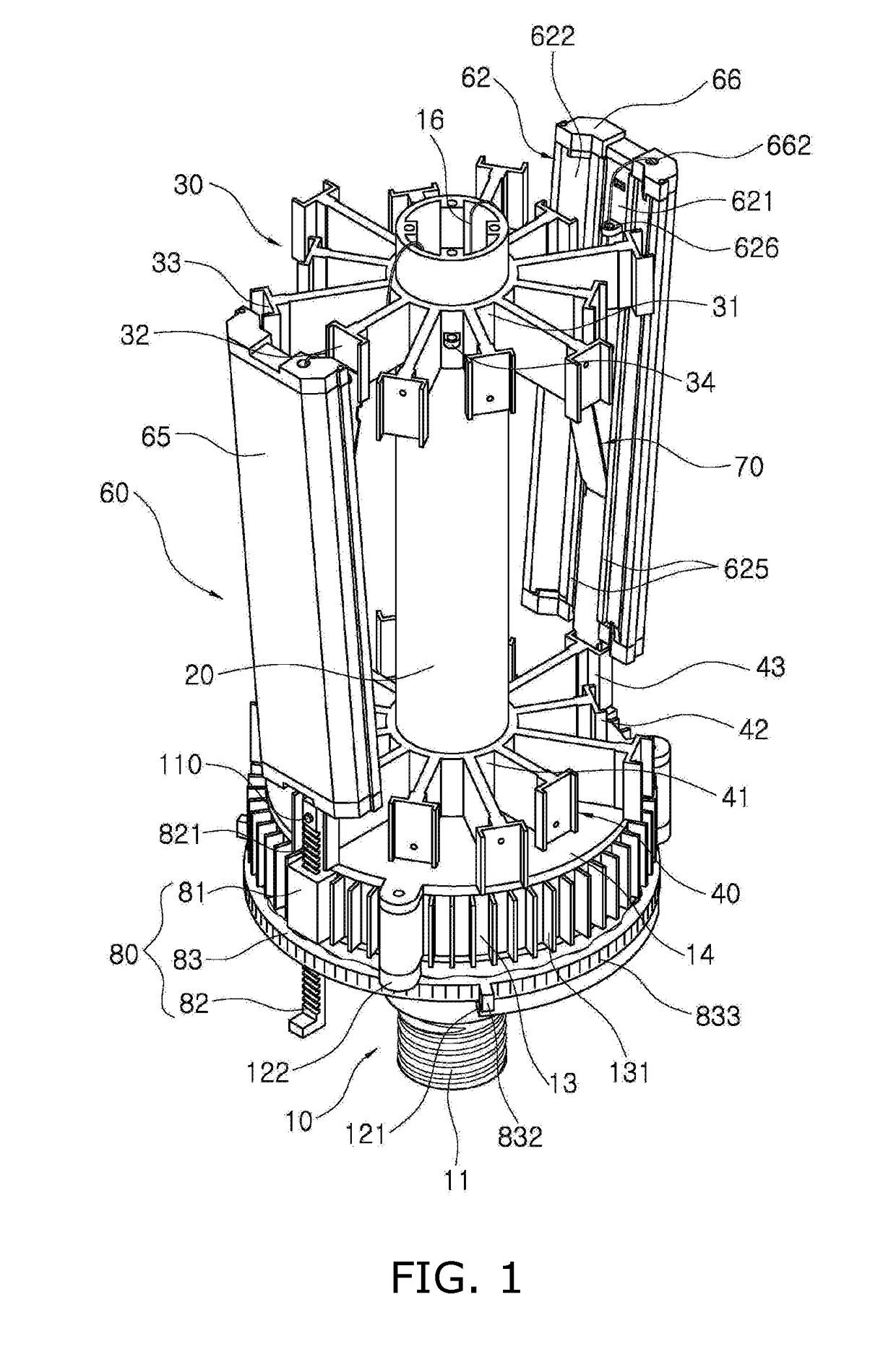
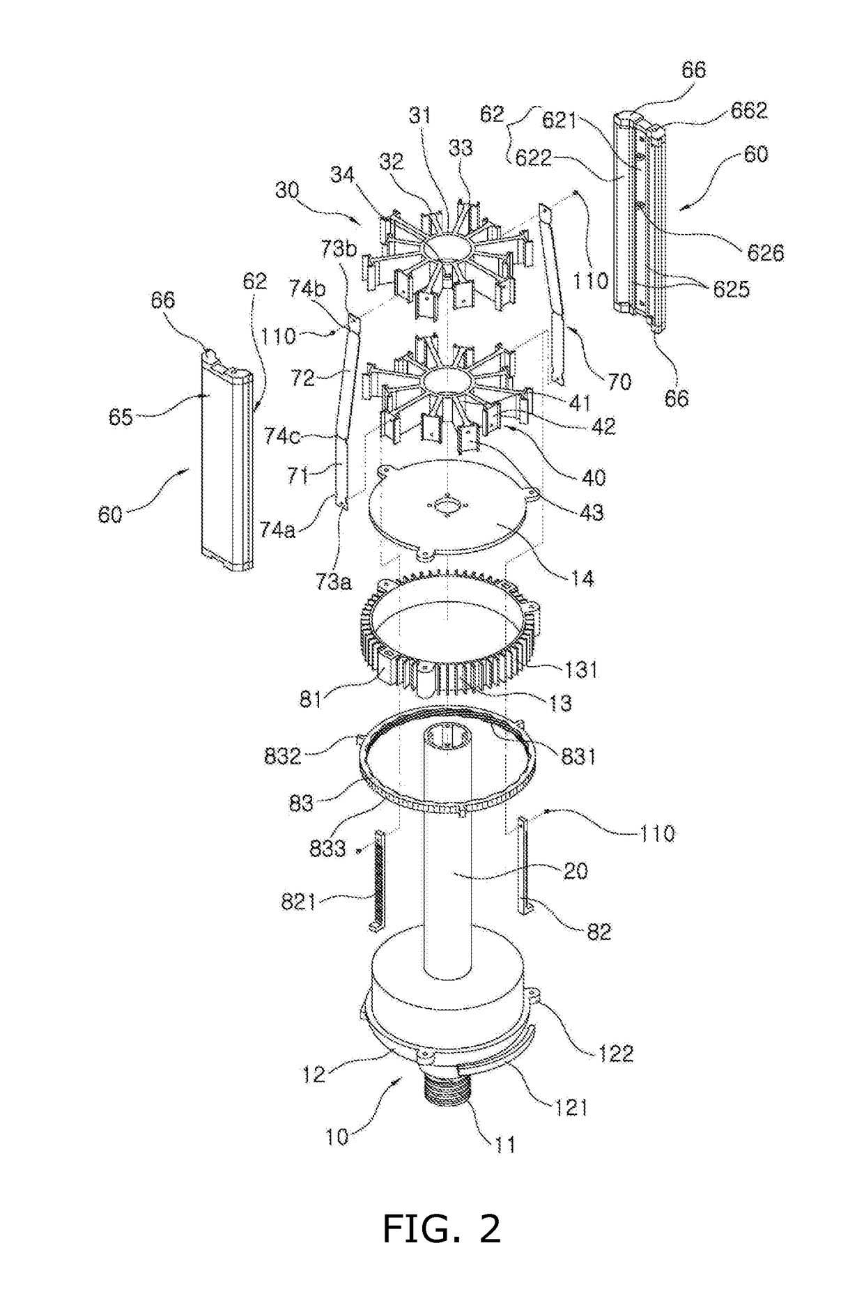
A LED (light-emitting diode)-based illumination assembly with an adjustable irradiation angle comprises a conductive threaded protrusion protruding from a hollow cylindrical body and threaded to an electrical bulb-type socket; a vertical elongate guide rod protruding from the base sub-assembly; a fixed LED-module support fixed to a distal end of the vertical elongate guide rod; a movable LED-module support configured to move along the vertical elongate guide rod; a plurality of LED-based illumination modules; a plurality of elongate elastic plate; an irradiation angle adjustment mechanism, wherein the irradiation angle adjustment mechanism is configured to allow operative connection between an outer circumferential surface of the hollow cylindrical body of the base sub-assembly and the movable LED-module support, wherein the irradiation angle adjustment mechanism is configured to allow adjustment of an irradiation angle of the LED-based illumination modules to a selected angle via the operative connection.

Description

CROSS-REFERENCE TO RELATED APPLICATION[0001]This application claims the benefit of Korean patent application No. 10-2016-0084623 filed on Jul. 5, 2016, the entire content of which is incorporated herein by reference for all purposes as if fully set forth herein.BACKGROUNDField of the Present Disclosure[0002]The present disclosure relates to a LED-based illumination assembly with an adjustable irradiation angle. More particularly, the present disclosure relates to a LED-based illumination assembly with an adjustable irradiation angle where, when a number of LED-based illumination modules are fabricated using light emitting diodes (LEDs) with low heat generation and low power consumption, and, then, using these modules, various lighting devices with lamp shapes (for example, a stairway light, a floodlight, a streetlight, a security light, a landscape light, an illumination light for illuminating a house or a house or a factory, etc.) are produced, a light irradiation angle of the LED-...

Claims


Application Information

Patent Timeline
IPC IPC(8): F21V21/14F21V14/02F21V15/01F21V3/02F21V23/00F21V17/16
CPCF21V21/14F21V23/001F21V17/16F21Y2115/10F21V29/77F21V3/02F21V14/02F21V15/01F21K9/232F21K9/65F21V3/00F21K9/23F21S10/026F21V29/70
Inventor SHIM, YOUNG CHEL
Owner SAEVIT ELECTRIC & LIGHTING CO LTD
Learn More