
Lamp control device and control method therefor

Active Publication Date: 2018-01-04
SILICON WORKS CO LTD +1
View PDF3 Cites 9 Cited by
  • Summary
  • Abstract
  • Description
  • Claims
  • Application Information

AI Technical Summary

Benefits of technology

This patent is about a lamp control device that can light up a vehicle's lamps in a sequential manner to improve its aesthetic appearance. The device can also switch the lamps to act as emergency lights when in response to a stop signal, improving driving safety and preventing accidents. Additionally, the device ensures stable operation of the LED modules, even when increasing the number of LED channels in the vehicle lamps.

Problems solved by technology

However, the increase in number of LED channels constituting the vehicle lamp or the increase in number of LEDs for each channel may be limited depending on the installation environment.
Furthermore, since each of the LED channels does not have uniform brightness, a light intensity difference may occur.
However, the lamp control device according to the related art may have a limit to the number of LED channels depending on the installation environment of a vehicle, and an error between parts may occur in offset or part arrangement.
Such an error between parts may cause a current deviation between LED channels, and the lamp control device according to the related art may not perform uniform brightness control between channels due to the current deviation.

Method used


Image

  • Lamp control device and control method therefor
  • Lamp control device and control method therefor
  • Lamp control device and control method therefor

Examples


first embodiment

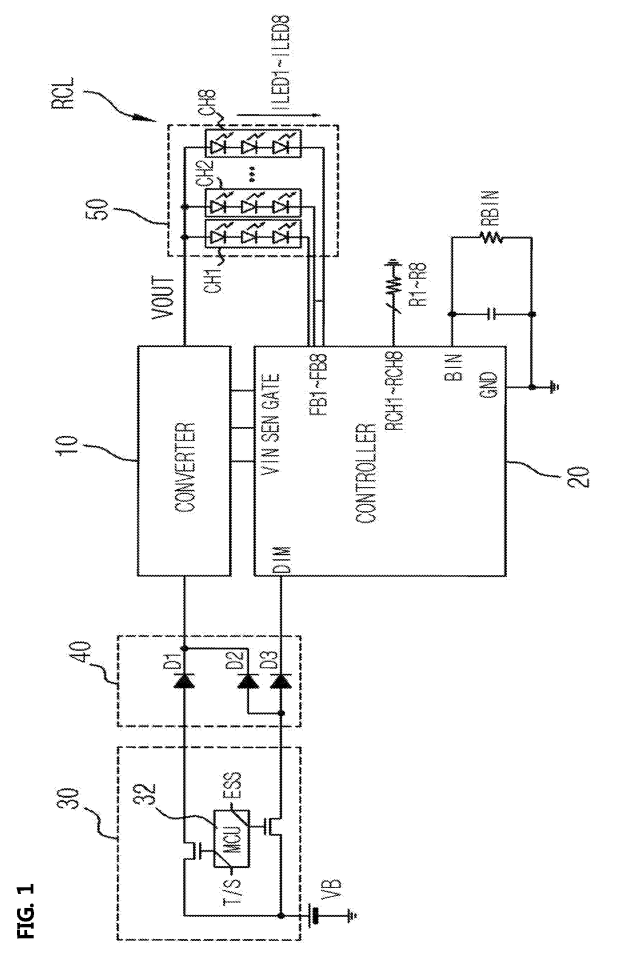
[0026]FIG. 1 illustrates a lamp control device according to the present invention.

[0027]Referring to FIG. 1, the lamp control device according to the first embodiment of the present invention includes a lamp RCL, a converter 10 and a controller 20.

[0028]The lamp RCL includes one LED module 50 having a plurality of LED channels. The plurality of channels in the LED module 50 may be arranged in parallel. FIG. 1 exemplifies that one controller 20 drives LEDs of first to eighth channels CH1 to CH8 included in the LED module 50. For example, the lamp RCL may include a brake lamp, a tail lamp, a turn signal lamp and an emergency stop lamp of a vehicle or correspond to a rear combination lamp having a composite function for notifying a braking operation, a taillight function, and an emergency stop.

[0029]The lamp RCL may be divided into a lamp installed only on the vehicle body and lamps distributed to the vehicle body and a trunk, depending on the type of the vehicle. The first embodiment ...

second embodiment

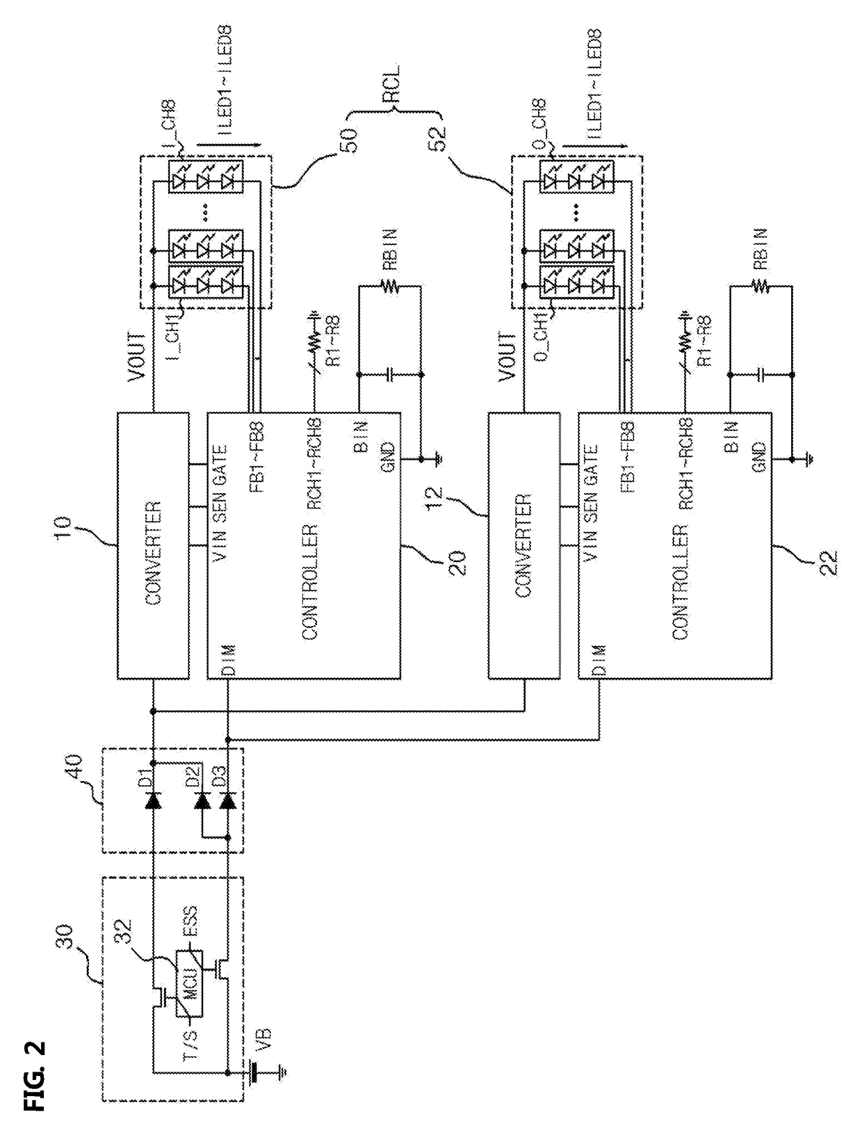
[0045]FIG. 2 illustrates a lamp control device according to the present invention, and FIG. 3 illustrates a turn signal lamp to which the configuration of FIG. 2 is applied.

[0046]Referring to FIG. 2, the lamp control device according to the second embodiment of the present invention includes a lamp RCL, converters 10 and 12 and controllers 20 and 22.

[0047]The lamp RCL includes LED modules 50 and 52 each having a plurality of LED channels. FIG. 2 exemplifies that the controller 20 drives LEDs of first to eighth channels I_CH1 to I_CH8 of the LED module 50 and the controller 22 drives LEDs of first to eighth channels O_CH1 to O_CH8 of the module 52.

[0048]The lamp RCL may be divided into a lamp installed only on a vehicle body and lamps distributed to the vehicle body and a trunk, depending on the type of a vehicle. The second embodiment may be applied to the lamps distributed to the vehicle body and the trunk as illustrated in FIG. 3. The second embodiment may also be applied to the l...


PUM


Abstract

A lamp control device may include: a lamp including an LED module having a plurality of LED channels; a converter configured to receive a voltage corresponding to a turn signal, convert the voltage into an output voltage and internal voltage, and supply the output voltage to the LED module; and a controller configured to start counting a preset delay time when the internal voltage is supplied from the converter, and control the plurality of LED channels to sequentially light up at intervals of the delay time.

Description

BACKGROUND1. Technical Field[0001]The present disclosure relates to a lamp control technology, and more particularly, to a lamp control device for a vehicle, which is capable of improving stability and functionality, and a control method thereof.2. Related Art[0002]In general, a vehicle employs vehicle lamps for various uses, and the vehicle lamps may include a head lamp and a rear combination lamp.[0003]Among the vehicle lamps, the read combination lamp includes a turn signal lamp, a brake lamp, a tail lamp and a back lamp, and is used to inform a driver in another vehicle of a driving intention and state of an ego vehicle, the vehicle following the ego vehicle.[0004]Recently, with the rapid development of high-brightness light emitting diodes (LED), various vehicle lamps employing the LEDs have been developed. As the LEDs are employed as a light source, the designs of the vehicle lamps are diversified, and the number of LEDs constituting each of the vehicle lamps tends to increase...

Claims


Application Information

Patent Timeline
IPC IPC(8): H05B33/08B60Q1/34B60Q1/44H05B37/02H05B44/00
CPCH05B33/0845B60Q1/34B60Q1/44B60Q1/2696H05B37/0281B60Q1/46B60Q1/26H05B33/0827H05B47/16H05B47/155B60Q1/2607H05B45/46Y02B20/40H05B45/10B60Q1/381F21S43/14B60Q1/52
Inventor HONG, JU PYOHA, JOO WANKIM, SUNG HWANLEE, JU HYUNJIN, HAI FENGYOO, TAE YOUNGQU, WANYUANLEE, SE WONJEONG, BYEONG HOPARK, HYUN II
Owner SILICON WORKS CO LTD
Learn More