Active sonar and control method for active sonar

a control method and active sonar technology, applied in the field of active sonar and a control method of active sonar, can solve the problems of difficult to acquire information in relation to a long-distance target, unclear vertical relationship between the elevation angle of the transmitted fan beam and the vertical relationship of the irradiation position at the target arrival, etc., and achieve high-quality information.

Active Publication Date: 2017-12-28
NEC CORP
View PDF10 Cites 5 Cited by
  • Summary
  • Abstract
  • Description
  • Claims
  • Application Information

AI Technical Summary

Benefits of technology

[0008]The use of the technique disclosed in patent document 1 or patent document 2 enables the acquisition of highly accurate information in relation to a short-distance target. In general cross fan beam methods, however, there has been a problem in that it is difficult to acquire information in relation to a long-distance target. In the case of the long-distance target, a plurality of transmitted fan beams transmitted at mutually different elevation angles propagate through mutually different propagation paths. This is because each transmitted fan beam is reflected or refracted in a deferent way depend on their elevation angle. As a result, for each transmitted fan beam, a difference occurs in the time to arrive at the same target. Further, there is a case where the correspondence between the elevation angles of the transmitted fan beams and the vertical relationship of the irradiation positions at the target arrival becomes unclear. For these reasons, the cross fan beam method has not been used in the acquisition of images of a long-distance target, and the application of the cross fan beam method has been limited to the acquisition of images of a short-distance target. Such a problem of the distance limitation has not been able to be eliminated even through the use of the techniques disclosed in patent documents 1 and 2.

Problems solved by technology

When the above-described cross fan beam method is simply used, there are some cases that accurate information cannot be obtained because of the modulations of the echo sounds or the interfusion of noises.
In general cross fan beam methods, however, there has been a problem in that it is difficult to acquire information in relation to a long-distance target.
Further, there is a case where the correspondence between the elevation angles of the transmitted fan beams and the vertical relationship of the irradiation positions at the target arrival becomes unclear.
For these reasons, the cross fan beam method has not been used in the acquisition of images of a long-distance target, and the application of the cross fan beam method has been limited to the acquisition of images of a short-distance target.
Such a problem of the distance limitation has not been able to be eliminated even through the use of the techniques disclosed in patent documents 1 and 2.

Method used


Image

  • Active sonar and control method for active sonar
  • Active sonar and control method for active sonar
  • Active sonar and control method for active sonar

Examples


first example embodiment

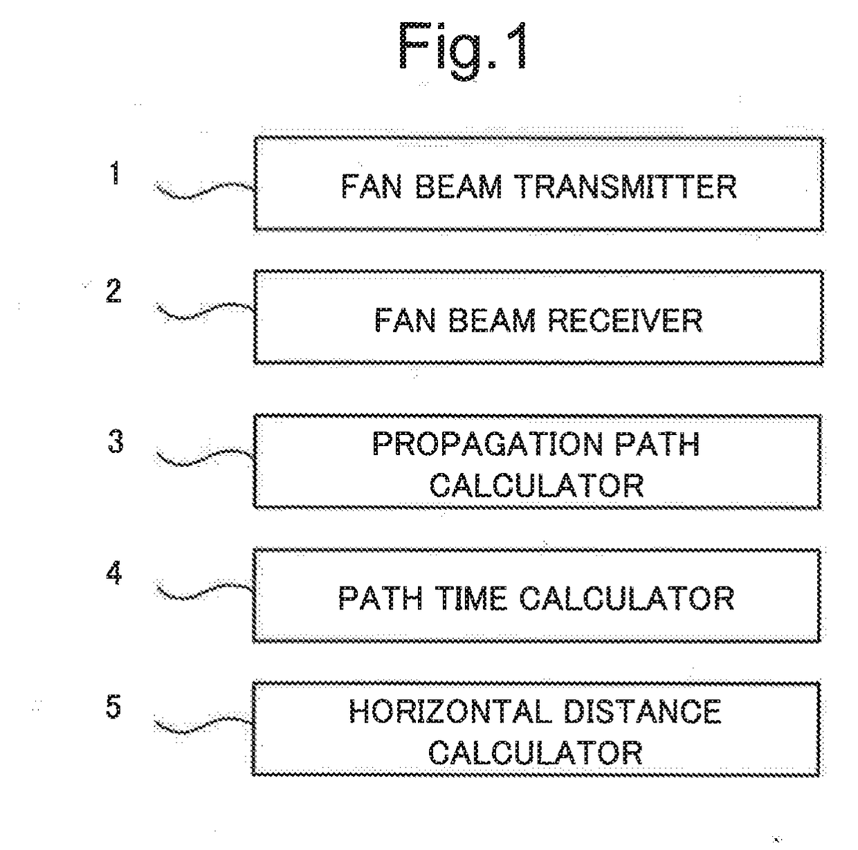
[0032]FIG. 1 is a block diagram illustrating the configuration of an active sonar according to this first example embodiment.

[0033]The active sonar includes a fan beam transmitter 1, a fan beam receiver 2, a propagation path calculator 3, a path time calculator 4, and a horizontal distance calculator 5.

[0034]The fan beam transmitter 1 transmits each of transmitted fan beams spreading widely in a horizontal direction and spreading narrowly in a vertical direction, with the elevation angle of each of the of the transmitted fan beams set to a corresponding one of mutually different elevation angles.

[0035]The fan beam receiver 2 receives each of received fan beams spreading widely in the vertical direction and spreading narrowly in the horizontal direction.

[0036]The propagation path calculator 3 calculates a propagation path of each of the transmitted fan beams based on the elevation angle of each of the transmitted fan beams and the profile of a medium. A typical medium is water (fresh...

second example embodiment

[0041]Before the description of an active sonar according to this second example embodiment, the outline of the cross fan beam method will be described below.

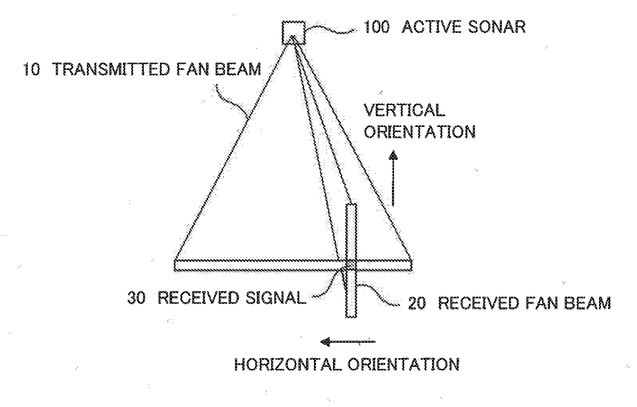
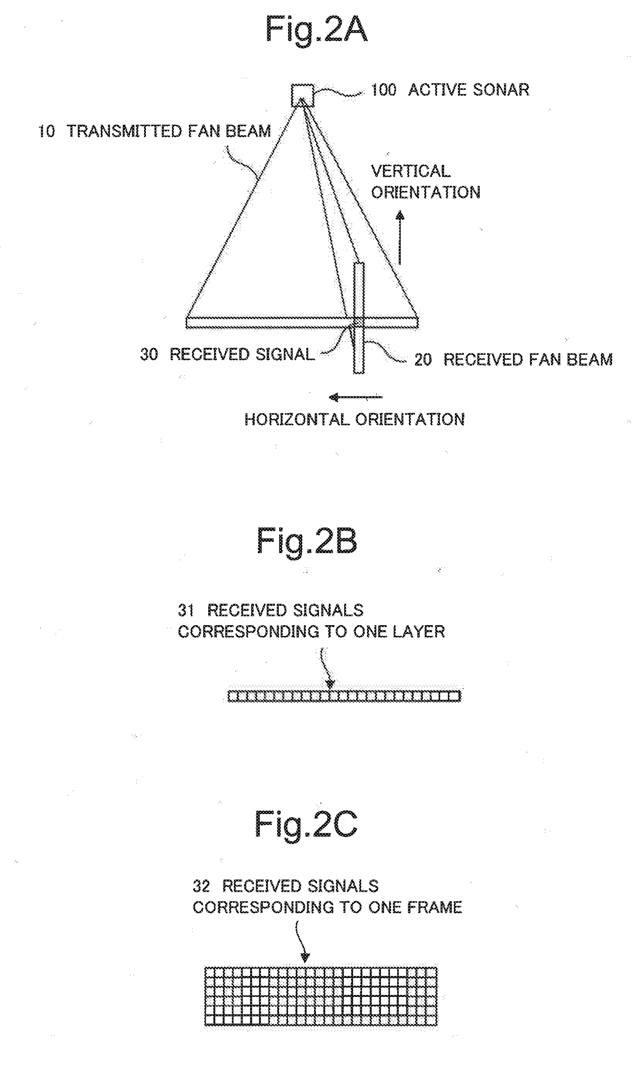
[0042]FIG. 2A, 2B, 2C, 2D are schematic diagrams for use in the description of the outline of the cross fan beam method. Firstly, as shown in FIG. 2A, an active sonar 100 transmits a transmitted fan beam 10. This transmitted fan beam 10 is wide in the horizontal direction and narrow in the vertical direction. The active sonar 100 transmits each of a plurality of the transmitted fan beams 10. Each transmitted fan beam 10 is transmitted with the orientation of the elevation-angle direction set to a corresponding one of mutually different orientations. Hereinafter, one of the transmitted fan beams will be also referred to as one layer. Next, the active sonar 100 receives an echo sound through a received fan beam 20. This received fan beam 20 is wide in the vertical direction and narrow in the horizontal direction. Under such a con...

third example embodiment

[0072]In this example embodiment, a specific and detailed configuration example of the active sonar will be described. FIG. 7 is a block diagram illustrating an example of the configuration of the active sonar according to this third present example embodiment. The active sonar includes a transmission unit 610, a reception unit 620, and a signal processing unit 630.

[0073]The transmission unit 610 includes a wave transmitter 611, a transmitted wave processing unit 612, a DAC 613, and a signal generator 614. Here, the DAC means a digital-to-analog converter.

[0074]The wave transmitter 611 converts an electrical signal into an acoustic wave signal, and transmits the acoustic wave signal into the water. The transmitted wave processing unit 612 cuts high frequency noise of a digital signal, and amplifies the electrical signal. The DAC 613 converts the digital signal output from the signal generator 614 into an analog signal. The signal generator 614 generates a digital waveform, such as a...


PUM


Abstract

In order to acquire echo sound information about a long-distance target, an active sonar comprises a fan beam transmitter, a fan beam receiver, a propagation path calculator, a path time calculator, and a horizontal distance calculator. The active sonar transmits a plurality of transmitted fan beams horizontally wide and vertically narrow, and the elevation angles of them are mutually deferent, and receives received fan beams vertically wide and horizontally narrow. The propagation path calculator calculates a propagation path of each of the transmitted fan beams based on the profile of medium and the elevation angle of the transmission. The path time calculator calculates a path time which is the time period from the transmission to the reception. The horizontal distance calculator calculates a horizontal distance from the active sonar to a generation source point of each echo sounds based on the propagation path and the path time.

Description

[0001]This application is based upon and claims the benefit of priority from Japanese Patent Application No. 2016-123200, filed on Jun. 22, 2016, the disclosure of which is incorporated herein in its entirety by reference.TECHNICAL FIELD[0002]The disclosed subject matter relates to an active sonar and a control method for the active sonar.BACKGROUND ART[0003]In underwater monitoring, an active sonar employing a cross fan beam method is known as a method for obtaining vertical-direction information of a target.[0004]Such an active sonar employing the cross fan beam method which transmits transmitted fan beams, each transmitted fan beam is narrow in a vertical direction (i.e., a water depth direction) and wide in a horizontal direction. And the active sonar transmits a plurality of transmitted fan beams whose elevation angles are mutually different. And receives received fan beams, each being, reversely to the case of the transmitted fan beams, wide in the vertical direction and narro...

Claims


Application Information

Patent Timeline
Patent Type & Authority Applications(United States)
IPC IPC(8): G01S15/42G01S15/66G01S15/02G01S15/04G10K11/00G01S15/89
CPCG01S15/42G01S15/66G01S15/89G10K11/006G01S15/025G01S15/04G01S15/86
Inventor KOBAYASHI, MINORU
Owner NEC CORP
Why Eureka
Try Eureka