
Dental furnace

a furnace and dental technology, applied in muffle furnaces, furnaces, lighting and heating apparatuses, etc., can solve the problems of adverse effects on the product quality of dental restoration parts, inevitably subjecting fresh fired dental restoration parts to vibration when the furnace base is lowered, etc., to achieve high quality expectations, high degree of dimensional accuracy, and the effect of long-lasting dental restoration parts

Active Publication Date: 2017-12-21
IVOCLAR VIVADENT AG
View PDF0 Cites 0 Cited by
  • Summary
  • Abstract
  • Description
  • Claims
  • Application Information

AI Technical Summary

Benefits of technology

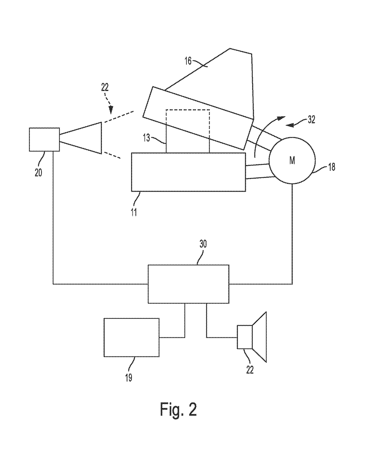
The invention is a dental furnace and process for controlling it that can create high-quality dental restoration parts with high accuracy and longevity. The dental furnace has a motor-activated furnace hood that allows for automatic closure and low-vibration opening at the end of the firing cycle. The furnace can also compensate for variations in ambient conditions by recording increased cooling and adjusting the furnace hood drive accordingly to avoid too rapid cooling. The dental furnace has a control device that allows for continuous comparison of the actual cooling-down rate of the object to be fired with the optimum cooling-down rate and can adjust the furnace hood opening to increase or decrease the cooling-down rate depending on the actual temperature of the object. This results in an optimal cooling cycle for the object without causing thermal tights or cracks.

Problems solved by technology

A stationary furnace hood with a furnace base which can be lowered with the help of a motor is basically just as suitable, however, this solution has the disadvantage that the freshly fired dental restoration parts are inevitably subjected to vibrations when the furnace base is lowered.
In any case, however, these vibrations have adverse effects on the product quality of the dental restoration part which is still in the process of cooling down.

Method used


Image

  • Dental furnace
  • Dental furnace
  • Dental furnace

Examples


Embodiment Construction

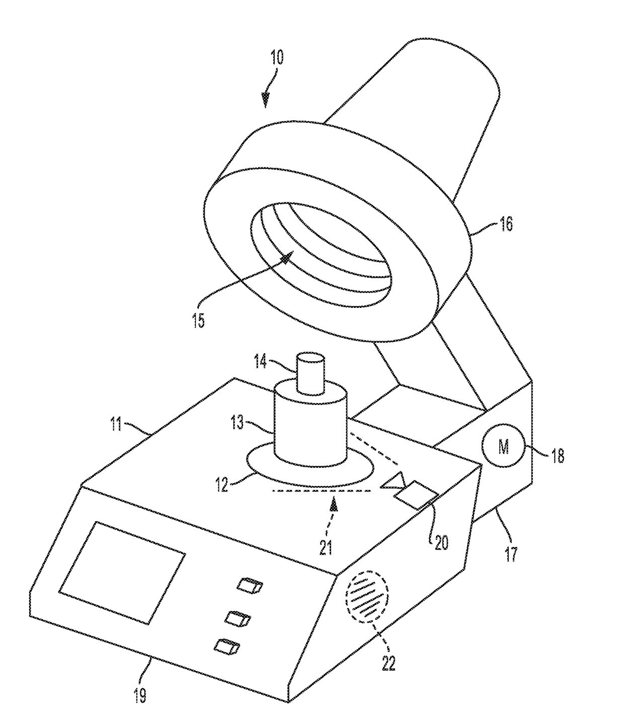
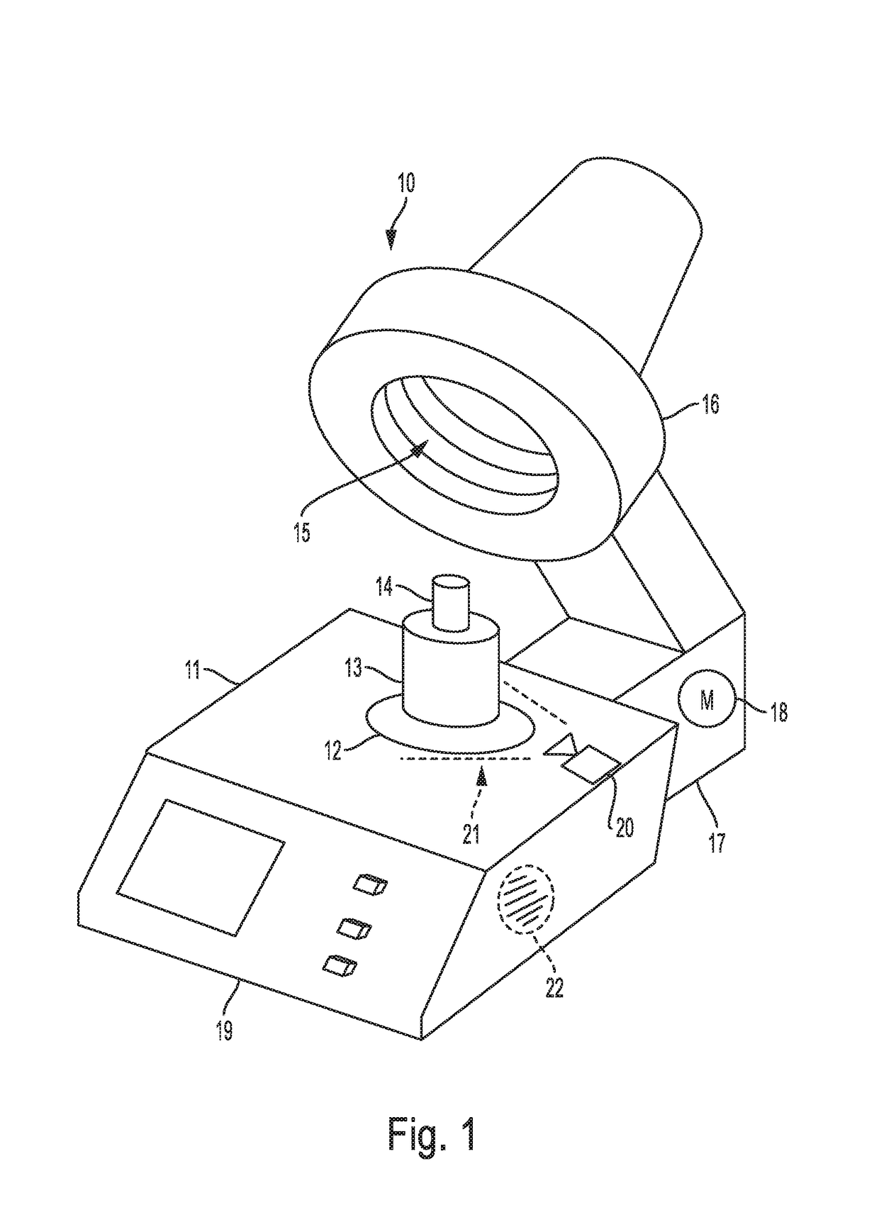
[0058]A dental furnace 10 comprises a furnace base 11 with a firing chamber bottom 12 which is destined to accommodate the object to be fired, for instance a muffle 13 (depicted here with workpiece 14 inserted). For firing, the object to be fired is accommodated in a firing chamber 15 which is depicted only schematically in FIG. 1 and which is provided in furnace hood 16 that is connected with furnace base 11 with the help of a joint 17. The degree to which furnace hood 16 is opened is adaptable via motor 18 which is only hinted in FIG. 1 for reasons of clarity. If the dental furnace 10 in accordance with the present invention is a pressing furnace, it additionally comprises, preferably in furnace hood 16, a device for pressing the dental material to be processed, the depiction of which, however, has been omitted here for the sake of more clarity.

[0059]Dental furnace 10 comprises moreover an operation device 19 which works in combination with a control device that is not depicted in...


PUM


Abstract

The invention concerns a dental furnace, with a furnace base and with a furnace hood, wherein the furnace hood includes a firing chamber for the accommodation of dental restorations, with a temperature sensor that records the temperature of the dental restoration and which is connected to a control device which controls the dental furnace, and the dental furnace (10) includes a drive unit (18) for the furnace hood (16) and the control device (30) controls the drive unit (18) based on the temperature recorded by the temperature sensor (20), namely opens the furnace hood.

Description

CROSS-REFERENCE TO RELATED APPLICATIONS[0001]This application is a continuation application and claims priority to U.S. application Ser. No. 14 / 367,299 filed on Jun. 20, 2014, which is the National Stage application of International patent application PCT / EP2013 / 073287 filed on Nov. 7, 2013, which claims priority to European patent application No. 12197055.2 filed on Dec. 13, 2012, the disclosures of which are incorporated herein by reference in their entirety.TECHNICAL FIELD[0002]The invention concerns a firing or pressing furnace for dental restorations having a furnace base, a furnace hood, wherein the furnace hood includes a firing chamber for the accommodation of dental restorations and a drive unit for the relative movement between the furnace hood and the furnace base, with a temperature sensor that records the temperature of the dental restorations and which is connected to a control device which controls the dental furnaceBACKGROUND OF THE INVENTION[0003]Such dental furnace...

Claims


Application Information

Patent Timeline
Patent Type & Authority Applications(United States)
IPC IPC(8): F27B17/02F27B5/18F27D21/00A61C13/20F27D11/02F27D19/00F27D21/02F27B5/06
CPCF27D2019/0003F27D21/0014F27D19/00F27B17/025A61C13/20F27D21/02F27D11/02F27B2005/068F27B5/18F27B17/02
Inventor JUSSEL, RUDOLF
Owner IVOCLAR VIVADENT AG
Learn More