
Stove

a technology for stoves and ovens, applied in the field of stoves, can solve the problems of floor draft and coldness in the room, fire consumes a lot of air in the room, and air must be replaced,

Active Publication Date: 2017-12-21
NIBE
View PDF3 Cites 6 Cited by
  • Summary
  • Abstract
  • Description
  • Claims
  • Application Information

AI Technical Summary

Benefits of technology

This patent describes a fireplace with a controlled air flow that helps the fire ignite faster. The fire is started by giving air underneath the firewood. When the fire is burning stably, the air flow is automatically reduced by a valve, and air is only supplied from above the fire to prevent it from burning too quickly. This allows the fire to be lit without needing to open the fireplace door. Additionally, the grate part can rotate, which makes it compact and allows the grate parts to move relative to each other without needing extra space.

Problems solved by technology

An open fire also consumes a lot of the air in the room and this air must be replaced, which occurs with cold air from outside that penetrates through slots in doors and windows.
This creates floor draft and coldness in the room.
However, modern houses are often very tight and designed with well defined active air removal system stipulating a specific air flow out of the house.
This under-pressure may also be caused by a strong kitchen fan.
In such a house, it would not be acceptable to have the stove door partly open; it would counteract the active air removal system and the under-pressure in the house would draw smoke from the fire into the indoor environment instead of the smoke being removed via the chimney.
Moreover, the habit of having the stove door partly open introduces safety hazards; a glow may jump out through the partly open stove door and cause a fire or the door may accidentally be opened fully introducing the risk of burning yourself on the fire.
However, it is difficult for the user to perform this regulation correctly to achieve an efficient burning of the fire wood through the duration of the burning of the firewood.
In any case it will result in a too rapid combustion of the firewood.
These automatically control methods are complex, difficult and expensive to manufacture.
Moreover, the above automatically controlled systems are difficult to combine with manual operation, which e.g. may be desired when adding firewood to an almost burnt out fire.

Method used


Image

  • Stove
  • Stove
  • Stove

Examples


Embodiment Construction

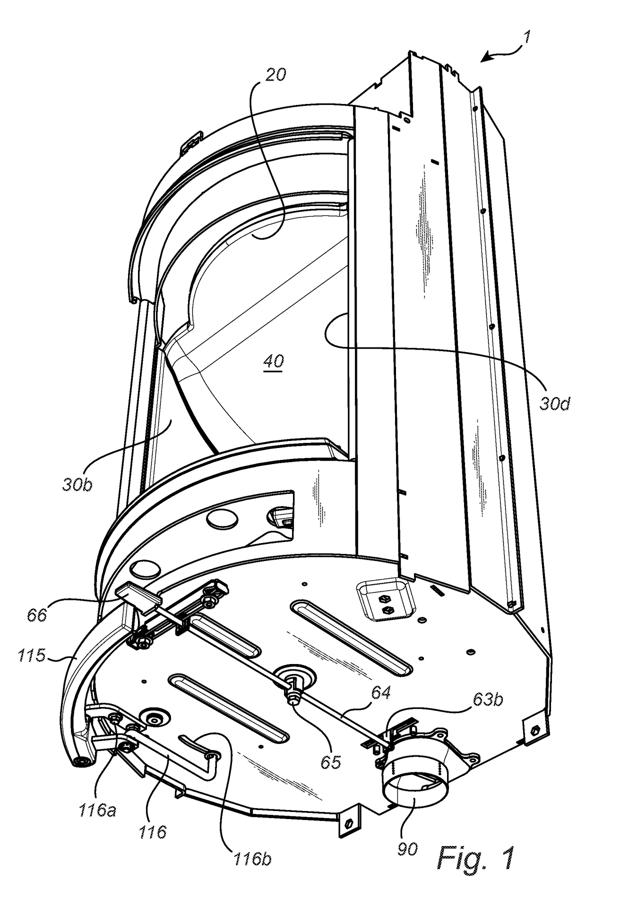
[0051]As shown e.g. in FIG. 1 and FIG. 4 the stove 1 adapted for indoor use comprises a housing having a bottom wall 10, a top wall 20 and one or more side walls 30a-d defining a combustion chamber 40 adapted to retain a fire. The stove 1 also comprises an air supply system 50 for supplying air to the combustion chamber 40.

[0052]The air supply system 50 comprises a primary air conduit 60 for supplying air to the combustion chamber 40 from below through the bottom wall 10 and a secondary air conduit 70 for supplying air to the combustion chamber 40 from above.

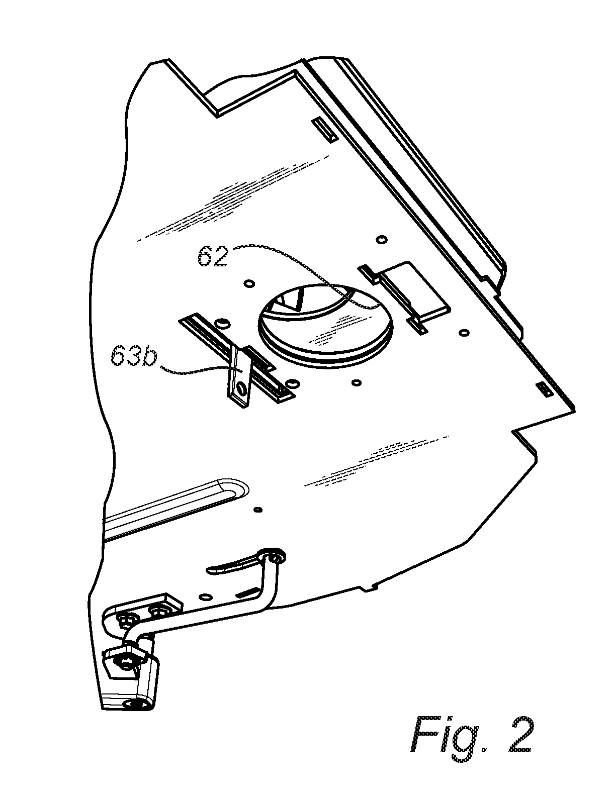
[0053]The primary and secondary air conduits 60, 70 are connected to a common inlet 61, The size of the common inlet 61 is adjustable. As shown in FIGS. 1, 2, 3a and 3b the size of the opening 62 of the common inlet 61 may be manoeuvred to be fully or partly covered, such as with a throttle or valve plate 63. The valve plate 63 is manually operable. This is accomplished by a lever 64 which interacts with an arm 63b attached to t...


PUM


Abstract

A stove for indoor use includes a housing having a bottom wall, a top wall and one or more side walls defining a combustion chamber adapted to retain a fire, and an air supply system for supplying air to the combustion chamber. The air supply system includes a primary air conduit for supplying air to the combustion chamber from below through the bottom wall and a secondary air conduit for supplying air to the combustion chamber from above. A valve is arranged in the primary air conduit or in a branching between the primary and secondary air conduits. The valve is controlled by a bimetal whereby the valve is in a maximum open position when the prevailing temperature is below a first predetermined temperature during start-up of a fire and in a maximum closed position when the prevailing temperature is above a second predetermined temperature after start-up of the fire.

Description

FIELD OF THE INVENTION[0001]The present invention relates to a stove for indoor use.BACKGROUND OF THE INVENTION[0002]An open fire has been used as a heating source in many homes since ancient times. However, in an open fire the fuel in form of firewood is consumed quickly and reproduces only a fraction of the energy in the form of radiant heat. Most of the energy disappears with the flue gases out through the chimney. An open fire also consumes a lot of the air in the room and this air must be replaced, which occurs with cold air from outside that penetrates through slots in doors and windows. This creates floor draft and coldness in the room.[0003]Today, we often use a stove instead of an open fire as a secondary heating source in our homes. In stoves, the combustion of fuel typically takes place in a closed combustion chamber, which is provided with air from outside through the wall or bottom plate. In order to have an effective combustion process, it is important to regulate the ...

Claims


Application Information

Patent Timeline
IPC IPC(8): F24H9/20F23N3/04F24H3/00
CPCF24H9/2085F24H3/006F23N2041/02F23N2025/16F23N2035/06F23N3/047F23N3/04F24B1/028F24B1/187F24B1/19F24B1/193F24B5/026F23H11/24F23N2225/16F23N2241/02F23N2235/06
Inventor DIURLIN, NILSKLARINSSON, CARL MARCUS ANDREAS
Owner NIBE
Learn More