
Pipe fitting, particularly for air conditioning, conditioning and refrigeration systems

a technology for air conditioning and refrigeration systems, applied in the direction of pipe connection arrangements, compression machines with non-reversible cycles, light and heating apparatus, etc., can solve the problems of gas permeation through the elastic ring b>3/b> toward the outside environment, degradation of the elastic properties of the wall, and reduced sealing compression, so as to ensure the reliability of the fitting over time and high gas tightness

Inactive Publication Date: 2010-04-08
MAFLOW
View PDF4 Cites 11 Cited by
  • Summary
  • Abstract
  • Description
  • Claims
  • Application Information

AI Technical Summary

Benefits of technology

[0012]The aim of the present invention is to provide a pipe fitting, particularly for air conditioning, conditioning and refrigeration systems, which offers high tightness for the gases inside the duct and ensures reliability of the fitting over time.
[0013]Within this aim, an object of the present invention is to provide a pipe fitting which avoids the permeability of the gas from the hose due to the aging of the hose and therefore due to the natural degradation of the elastic properties of the wall of the rubber hose.
[0014]Another object of the present invention is to provide a pipe fitting in which the cost of the assembly obtained by the coupling of a hose is lower than that of the solution with elastic rings.
[0015]Still another object of the present invention is to provide a pipe fitting which is highly reliable, relatively simple to provide and at competitive costs.

Problems solved by technology

However, the drawback is that the gas permeates through the elastic ring 3 toward the outside environment.
However, since there is no adhesion between the adhesive solution 4 and the inner thermoplastic layer of the rubber hose 1, over time the natural degradation of the elastic properties of the wall of the hose entails a reduced sealing compression at the interface, until the adhesive solution 4 partially separates from the wall of the rubber hose 1, causing leakage of gas from the duct.

Method used


Image

  • Pipe fitting, particularly for air conditioning, conditioning and refrigeration systems
  • Pipe fitting, particularly for air conditioning, conditioning and refrigeration systems
  • Pipe fitting, particularly for air conditioning, conditioning and refrigeration systems

Examples


Embodiment Construction

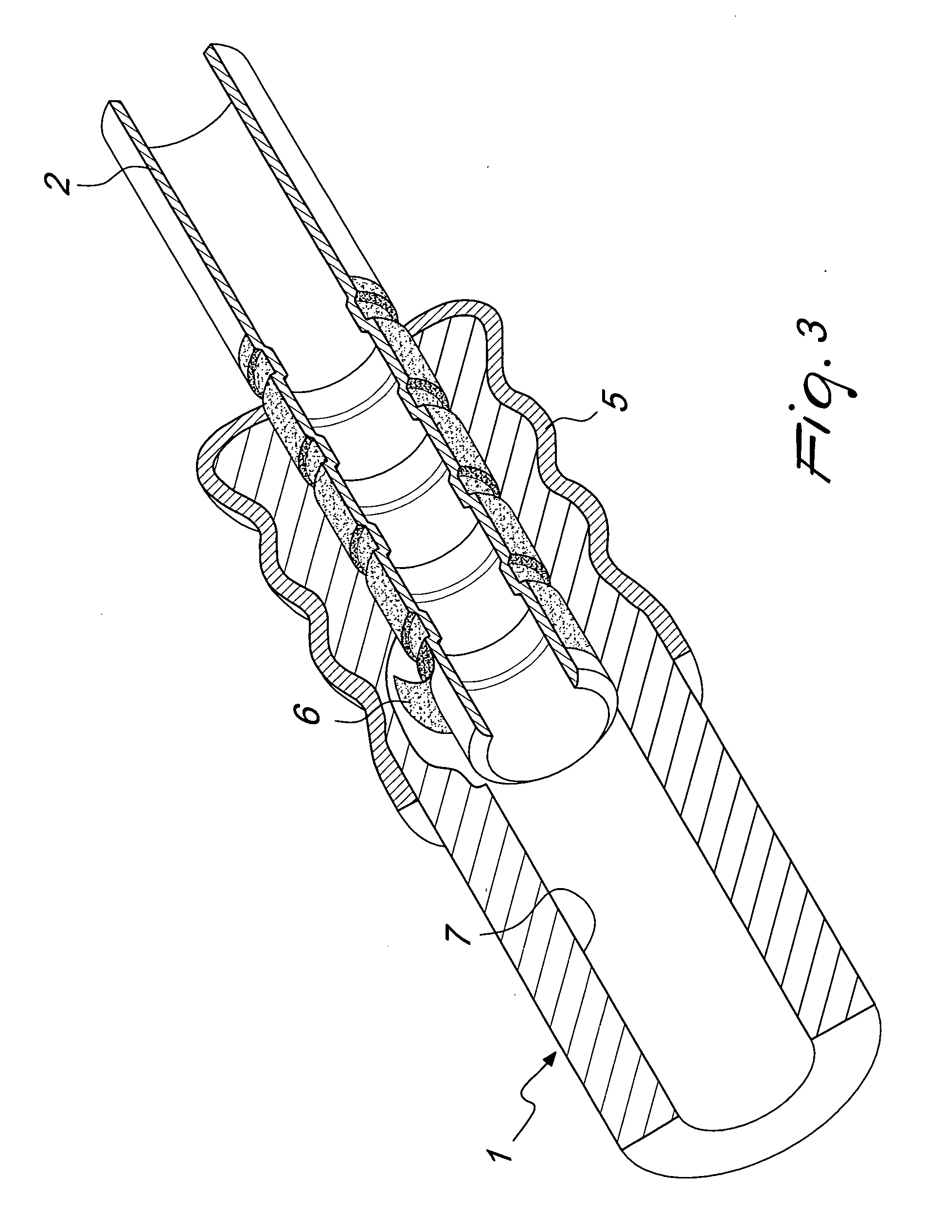
[0021]With reference only to FIG. 3, since FIGS. 1 and 2 have already been described and discussed previously, and using identical reference numerals for identical elements in all the figures, the fitting according to the present invention comprises, for a hose 1 with a rigid insert 2 with a corresponding bell-shaped element 5, the use of a double-adhesive solution 6 which is arranged on the surface of the rigid insert 2 and is capable of creating adhesion with both interfaces, i.e., the surface of the rigid insert 2 and the internal surface 7 of the rubber hose 1, with a substrate made of thermoplastic material.

[0022]The fact that a double-adhesive solution 6 is used combines the advantages of both solutions of the prior art described earlier, since it allows high gas tightness inside the duct and at the same time allows reliable durability, since thanks to the adhesion with both surfaces the hose 1 and the insert 2 become monolithic (regardless of the natural degradation of the el...


PUM

PropertyMeasurementUnit
Temperatureaaaaaaaaaa
Adhesion strengthaaaaaaaaaa

Abstract

A pipe fitting for rubber hoses, of the type with a thermoplastic substrate, particularly for air conditioning, conditioning and refrigeration systems, particularly for vehicles and the like, comprising a rigid insert which is adapted to be inserted in a hose to be connected, and a bell-shaped element which is adapted to be crimped around the hose, its particularity consisting in that it comprises a double-adhesive solution which is arranged on the outer surface of said rigid insert and is adapted to produce adhesion between said rigid insert and said thermoplastic material of said internal layer of the rubber hose.

Description

[0001]The present invention relates to a pipe fitting, particularly for air conditioning, conditioning and refrigeration systems, particularly for vehicles.BACKGROUND OF THE INVENTION[0002]As is known, current attention is increasingly directed toward reducing the greenhouse effect, and this compels to search continuously for innovative solutions for fluid conveyance lines aimed at reducing the leaks from such lines. In particular, a key point of the fitting is the connection interface between rubber hoses (which predominantly have a substrate, i.e., the innermost layer, made of thermoplastic material) and rigid lines (predominantly metallic).[0003]As is known, the flexible lines of air conditioning, refrigeration and conditioning systems typically use low-permeability hoses with a substrate made of thermoplastic material.[0004]In these cases, in order to ensure tightness with respect to the refrigerating gas in the interface between the hose and the fitting it is possible to use tw...

Claims


Application Information

Patent Timeline
IPC IPC(8): F16L33/18
CPCF16L33/34F16L33/2076F16L47/02F16L33/207F16L33/18F25B1/00
Inventor CARICCIA, GIANLUCACITELLI, MARCODOLENTE, GIANLUCASALVIA, VICENZO
Owner MAFLOW
Learn More