
In-vehicle structure of electric-power converter

a technology of electric power converter and in-vehicle structure, which is applied in the direction of electric devices, vehicular safety arrangments, vehicle sub-unit features, etc., can solve the problems of difficult to secure the space in which the signal connector is placed, the front face is not suitable for protecting the signal connector, and the discharge circuit might not operate appropriately. , to achieve the effect of reducing the possibility of signal connector damag

Inactive Publication Date: 2017-12-14
TOYOTA JIDOSHA KK
View PDF5 Cites 15 Cited by
  • Summary
  • Abstract
  • Description
  • Claims
  • Application Information

AI Technical Summary

Benefits of technology

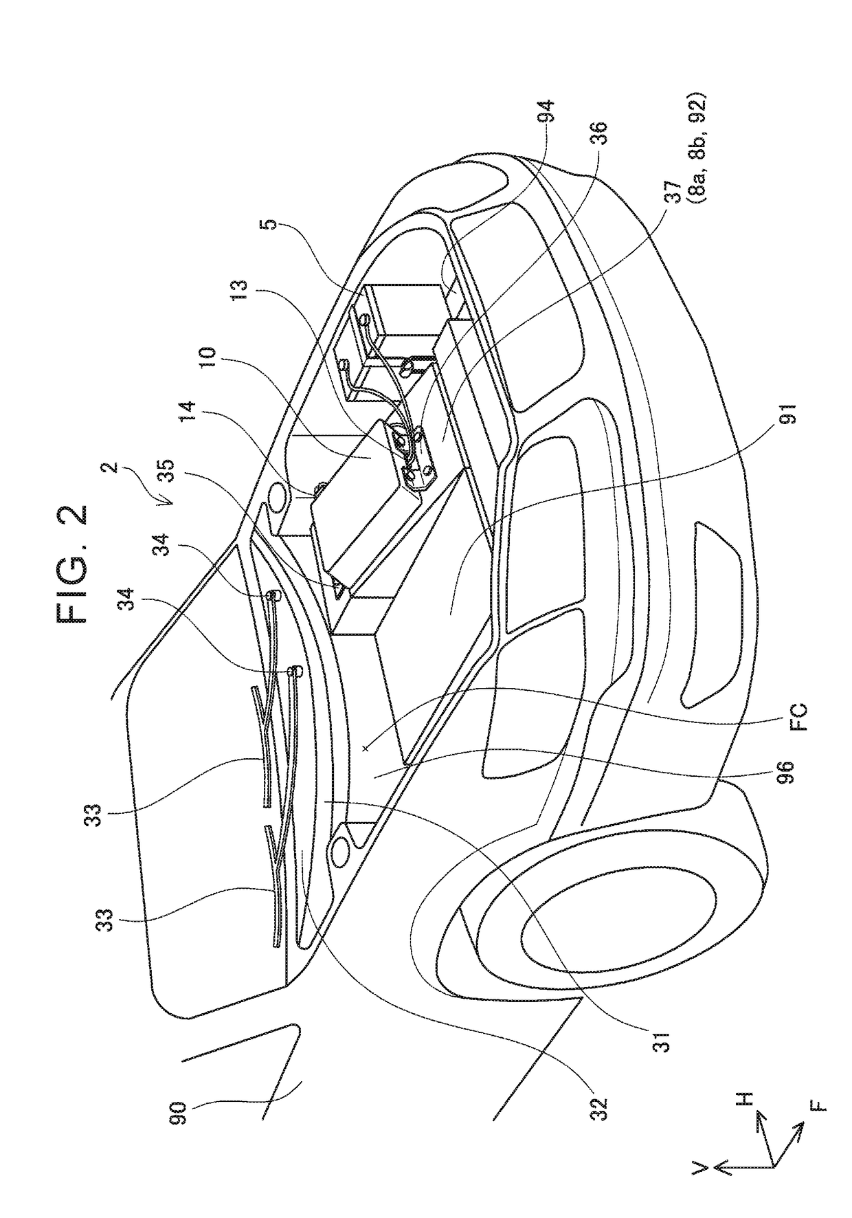
The present patent describes an in-vehicle structure for an electric-power converter that converts electric power into driving power for a traction motor. The structure is designed to prevent damage to the signal connector that sends a discharge instruction signal in the event of a collision. The signal connector is placed on the side face of the electric-power converter, facing in the vehicle width direction, so that it is less likely to come into contact with the cowl top of the motor housing. This reduces the likelihood of damage to the signal connector and ensures proper operation of the discharge circuit.

Problems solved by technology

When the signal connector makes contact with the cowl top, the signal connector is damaged, so that a discharge instruction signal transmitted via the signal connector might not reach a discharge circuit and the discharge circuit might not operate appropriately.
However, the front face easily receives an impact at the time of a front collision, so the front face is not suitable for protection of the signal connector.
Accordingly, in a range, of the rear face, which is lower than the cowl top, it might be difficult to secure a space in which the signal connector is placed.

Method used


Image

  • In-vehicle structure of electric-power converter
  • In-vehicle structure of electric-power converter
  • In-vehicle structure of electric-power converter

Examples


Embodiment Construction

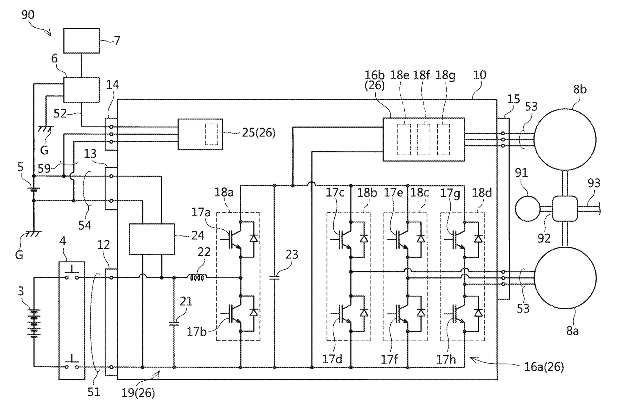
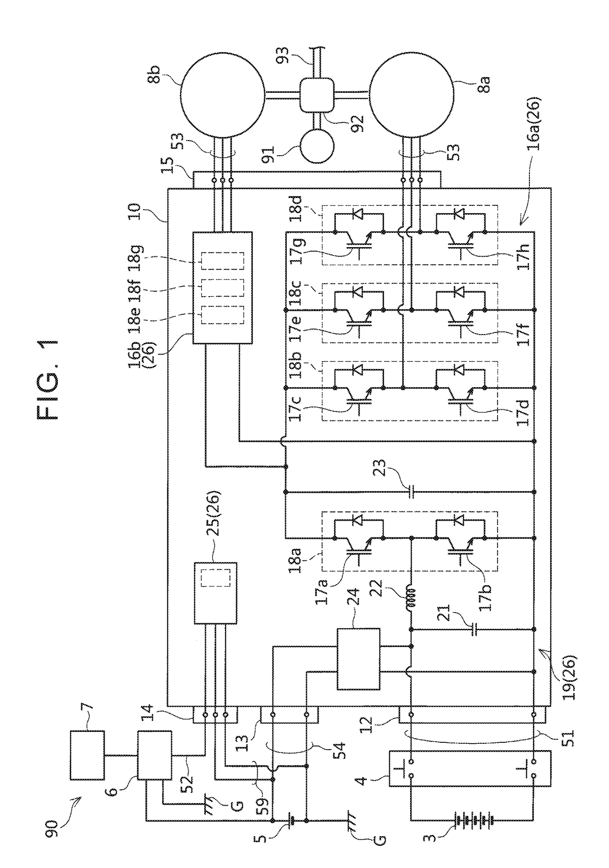
[0020]The following describes an in-vehicle structure of an embodiment with reference to the drawings. The in-vehicle structure of the embodiment is applied to a hybrid vehicle including two motors and one engine for traveling. FIG. 1 illustrates a block diagram of a driving system of a hybrid vehicle 90. Output shafts of two motors 8a, 8b and an output shaft of an engine 91 are connected to a power distribution mechanism 92. The power distribution mechanism 92 combines output torques of the motors 8a, 8b and an output torque of the engine 91 appropriately, and transmits a resultant torque to an axle 93. The power distribution mechanism 92 is more specifically a planetary gear, and the motor 8a is connected to its sun gear, the engine 91 is connected to its carrier, and the motor 8b and the axle 93 are connected to its ring gear. The power distribution mechanism 92 may transmit a part of the torque of the engine 91 to the motor 8a and may transmit a remaining torque to the axle 93. ...


PUM


Abstract

In an in-vehicle structure described in the present specification, an electric-power converter is fixed onto a transaxle and positioned in front of a cowl top. The electric-power converter includes a capacitor configured to restrain a high-frequency fluctuation in a voltage of electric power supplied from a battery, and a discharge circuit configured to discharge the capacitor. A connector (a signal connector) to which a wiring harness for communication of a discharge instruction signal to operate the discharge circuit at a time of a collision is connected is provided on a side face of the electric-power converter, the side face of the electric-power converter being facing in a vehicle width direction.

Description

INCORPORATION BY REFERENCE[0001]The disclosure of Japanese Patent Application No. 2016-117126 filed on Jun. 13, 2016 including the specification, drawings and abstract is incorporated herein by reference in its entirety.BACKGROUND1. Technical Field[0002]The present disclosure relates to an in-vehicle structure of an electric-power converter that converts electric power of an electric power source into driving electric power for a traction motor.2. Description of Related Art[0003]An electric vehicle includes an electric-power converter configured to convert electric power of an electric power source into driving electric power for a traction motor. Note that the “electric vehicle” in the present specification includes not only an automobile provided with only an electric motor as a power source, but also an automobile provided with both a motor and an engine configured to generate a driving force for traveling. Further, the “electric vehicle” described in the present specification al...

Claims


Application Information

Patent Timeline
Patent Type & Authority Applications(United States)
IPC IPC(8): B60L11/18B60K6/22H02P27/06B60L3/00H02M7/537
CPCB60L11/1803B60L3/00B60L11/1851B60K6/22H02P27/06B60Y2400/11Y10S903/904B60Y2200/91B60Y2200/92B60Y2400/61H02M7/537B60L53/22B60L15/007H02M7/003B60L2210/12B60L2210/14B60K1/00B60L3/0007B60L3/0015B60L3/04B60K2001/003B60Y2306/01B60Y2400/304B60Y2410/115B60Y2400/3042Y02T90/16B60L50/51B60L58/10Y02T10/64Y02T10/70Y02T10/7072Y02T90/14H02M1/322H05K7/14322H02K11/33B60L53/16B62D25/081B60R2021/0004B60R2021/0009B60K1/02H05K7/1432
Inventor BABA, RYUSUKEYAMANAKA, KENSHI
Owner TOYOTA JIDOSHA KK
Learn More