
Method of Driving Display Device Capable of Scanning Image

a display device and image technology, applied in static indicating devices, acquiring/reconfiguring fingerprints/palmprints, instruments, etc., can solve the problems of increasing the volume of portable devices, increasing the security of personal portable devices such as smartphones and table personal computers, and achieving the effect of improving the visibility of display devices and increasing the size of detection signals

Inactive Publication Date: 2017-12-07
CRUCIALTEC
View PDF8 Cites 50 Cited by
  • Summary
  • Abstract
  • Description
  • Claims
  • Application Information

AI Technical Summary

Benefits of technology

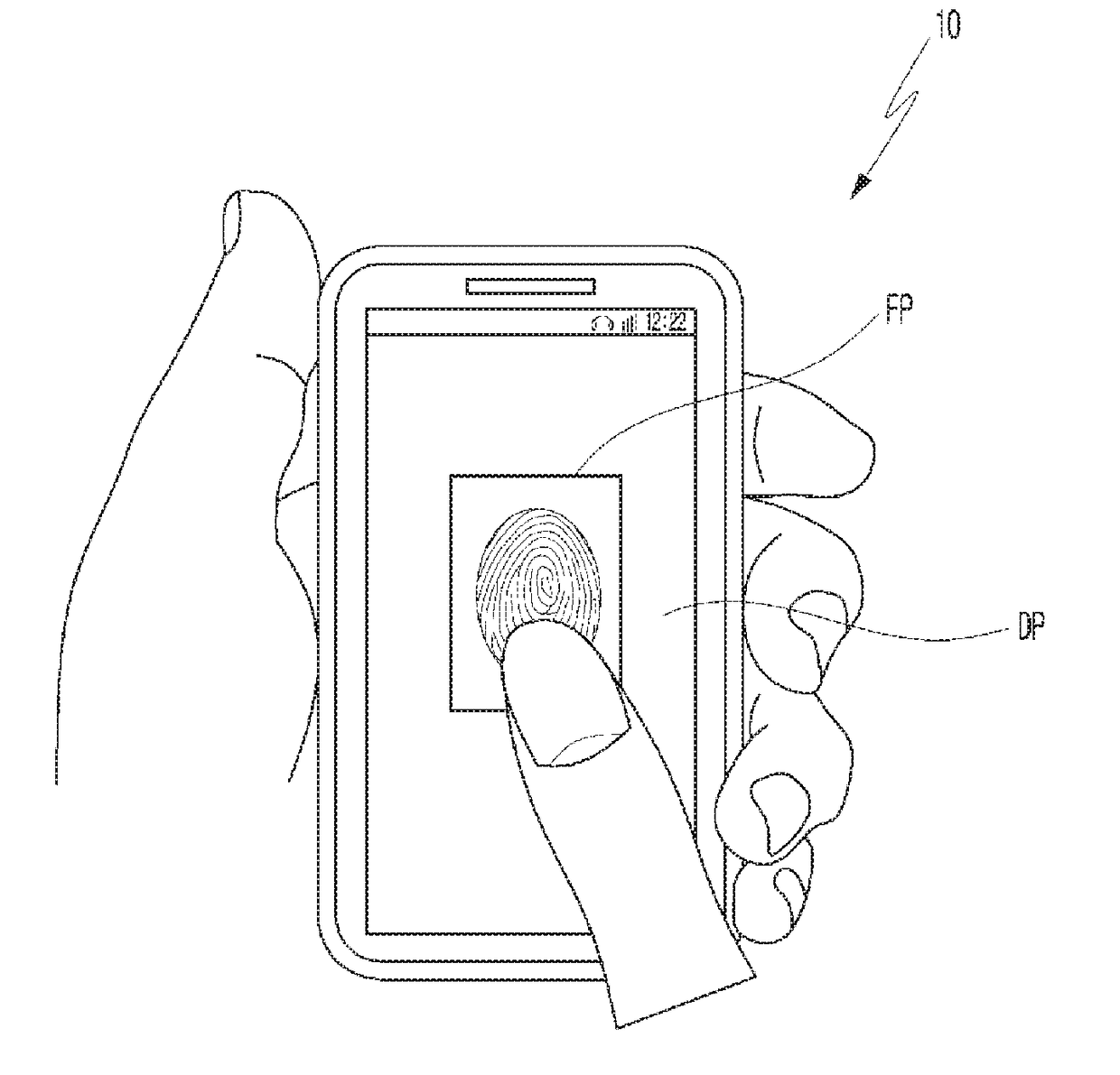
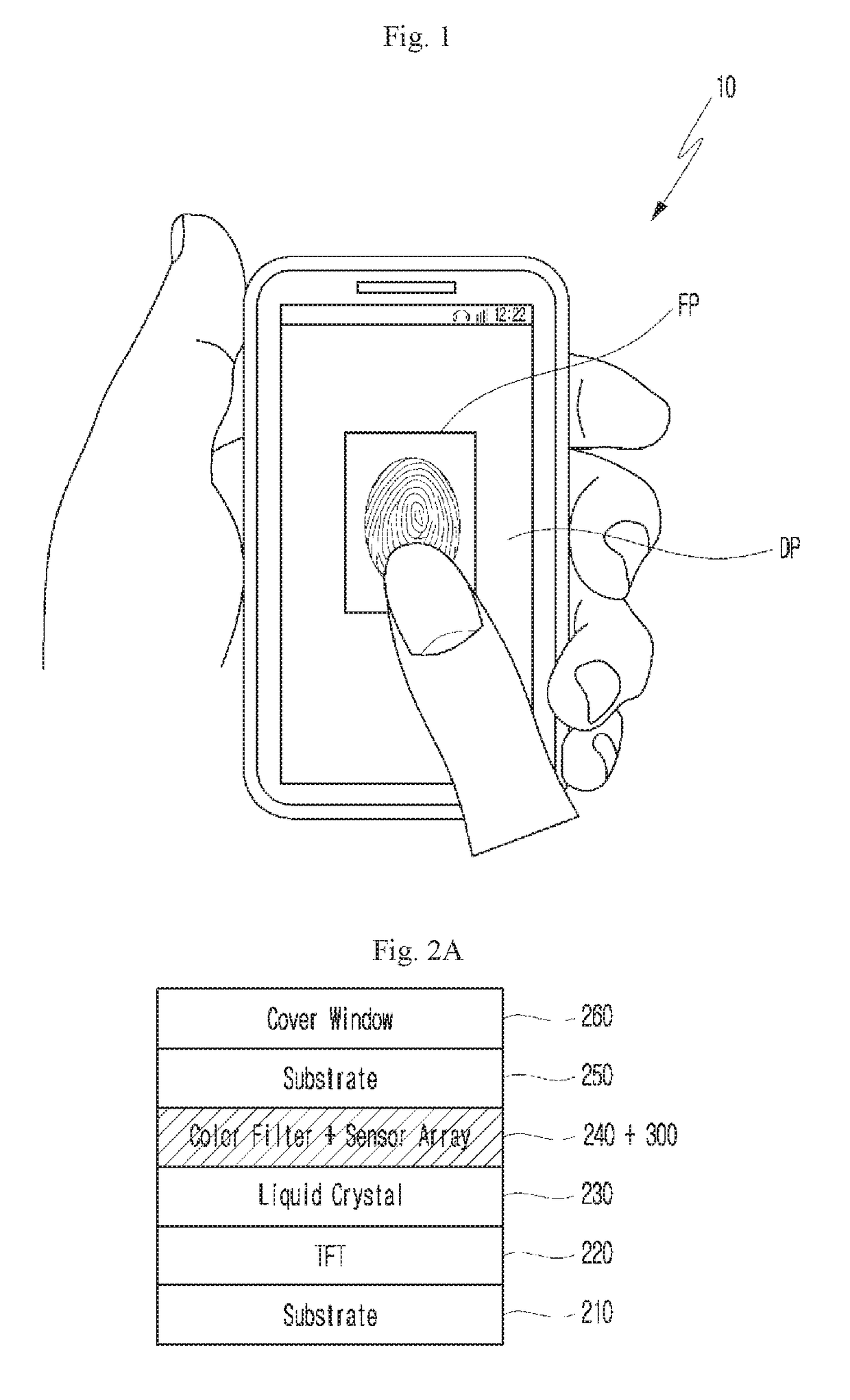
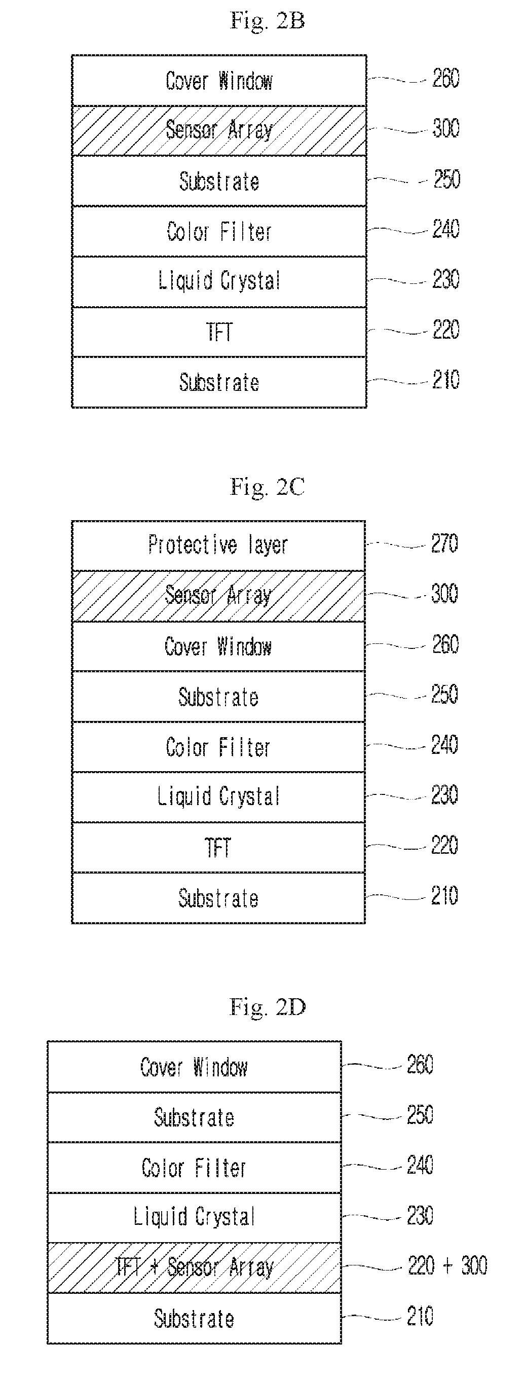
This patent describes a technology that improves the size and visibility of a detection signal by using a coupling phenomenon in a transistor and a peripheral circuit configuration. It also suggests using a transparent electrode to improve the display device's visibility. Additionally, it introduces a touch sensor that matches the size of a display screen pixel unit to enable sensing of images on the display. The technology also includes a protective layer that can scan user's fingerprint by detecting currents associated with touch capacitances of the user's fingerprint.

Problems solved by technology

Meanwhile, as security-related problems are coming into the fore nowadays, security of personal portable devices such as a smartphone and a table personal computer (PC) is becoming an issue.
Accordingly, there is a problem in that a volume of a portable device is increased.

Method used


Image

  • Method of Driving Display Device Capable of Scanning Image
  • Method of Driving Display Device Capable of Scanning Image
  • Method of Driving Display Device Capable of Scanning Image

Examples


Embodiment Construction

[0066]Hereinafter, exemplary embodiments of the present disclosure will be described in detail with reference to the accompanying drawings in order to enable one of ordinary skill in the art to which the present disclosure pertains to easily embody the disclosure. The present disclosure may be implemented in various different forms and is not limited to embodiments described herein. To clearly describe the present disclosure, parts unrelated to the description have been omitted from the drawings, and like reference numerals are given to like or similar elements throughout. Because a size and a thickness of each element illustrated in the drawings are arbitrarily shown for convenience of description, the present disclosure is not necessarily limited to what is illustrated in the drawings.

[0067]In the present disclosure, being “on-” signifies being disposed above or below a target member and does not necessarily mean being disposed on an upper portion based on the direction of gravity...


PUM


Abstract

Disclosed in the present specification is a method for driving a display device capable of scanning an image, the display device comprising: a display module including a plurality of unit pixels arranged in a display area in which an image is displayed; and a contact sensor module forming a sensing area, which overlaps with the display area, and including at least one contact sensor respectively corresponding to the unit pixels, and the method comprising: a sensing mode identification step of identifying a sensing mode of the display device; a contact sensor selection step of selecting contact sensors to be activated, according to the identified sensing mode; and a contact sensor activation and sensing step of activating the selected contact sensors and receiving sensing signals from the activated contact sensors.

Description

TECHNICAL FIELD[0001]The present disclosure relates to a method of driving a display device capable of scanning an image.BACKGROUND ART[0002]A touch screen panel is a device for inputting a user command by a letter or a figure displayed on a screen of an image display device coming into contact with a person's finger or other contact means, and is used by being attached to an upper portion of the image display device. The touch screen panel converts a contact position touched by a person's finger and the like into an electrical signal. The electrical signal is used as an input signal.[0003]A touch detecting method in a touch screen panel has various types such as a resistive film method, an optical method, a capacitance method, and an ultrasonic method. Among these, in the capacitance method, whether a touch is generated is detected using a capacitance which changes when a touch generator comes into contact with a screen of a display device. A touch screen panel using the capacitanc...

Claims


Application Information

Patent Timeline
IPC IPC(8): G06F3/041G06K9/00G06F3/044H01L27/32
CPCG06F3/0412H01L27/32G09G2300/0439G06K9/001G06K9/0008G06F3/044H10K71/00H10K59/65H10K71/233G06F3/0416G09G3/2092G06F2203/0338G09G2300/0426G06F21/32G06F3/0443G06V40/1306G09G3/20G09G3/3648G09G3/3225G02F1/13338H01L29/786H01L27/14609H10K59/84H10K59/40G06V40/1359G06V40/1376H10K59/00
Inventor KIM, JONG UKJEON, HO SIK
Owner CRUCIALTEC
Learn More