
Colored photovoltaic modules

a photovoltaic module and color technology, applied in the direction of basic electric elements, electrical equipment, semiconductor devices, etc., can solve the problems of reducing the color appearance provided by the additional structure, affecting the effect of the so as to facilitate the desired color appearance of the pv module and reduce the amount of reflection loss

Inactive Publication Date: 2017-11-30
SOLARCITY
View PDF3 Cites 13 Cited by
  • Summary
  • Abstract
  • Description
  • Claims
  • Application Information

AI Technical Summary

Benefits of technology

This patent discusses various ways to improve the performance of a photovoltaic (PV) module. One way is to use a textured back surface that can be adjusted to control the amount of reflection loss. This helps to reduce glare and improve the module's overall appearance. Another way to improve the module is by using a color filter structure that produces a desired color appearance when viewed from the front surface of the transparent substrate. The color appearance is not significantly affected by viewing angle. The patent also mentions the use of an interlocking mechanism and an antireflective coating to further enhance the performance of the PV module.

Problems solved by technology

However, these extra structures can have a strong absorption of the sunlight thereby causing significant power loss to the PV modules.
Moreover, the color appearance provided by these additional structures tends to degrade over time.
The design of these films is often complex and therefore this technique may not be cost-effective for mass production.
Furthermore, the color appearance achieved by the coatings over the PV modules or the solar cells is typically angle-sensitive and can also degrade over time under environmental stresses (such as marine weather).
Moreover, applying extra coatings over the PV modules or the solar cells can introduce additional integration complexity, higher automation cost, and plasma damage to the solar cells.

Method used


Image

  • Colored photovoltaic modules
  • Colored photovoltaic modules
  • Colored photovoltaic modules

Examples


embodiments and examples

Detailed Embodiments and Examples

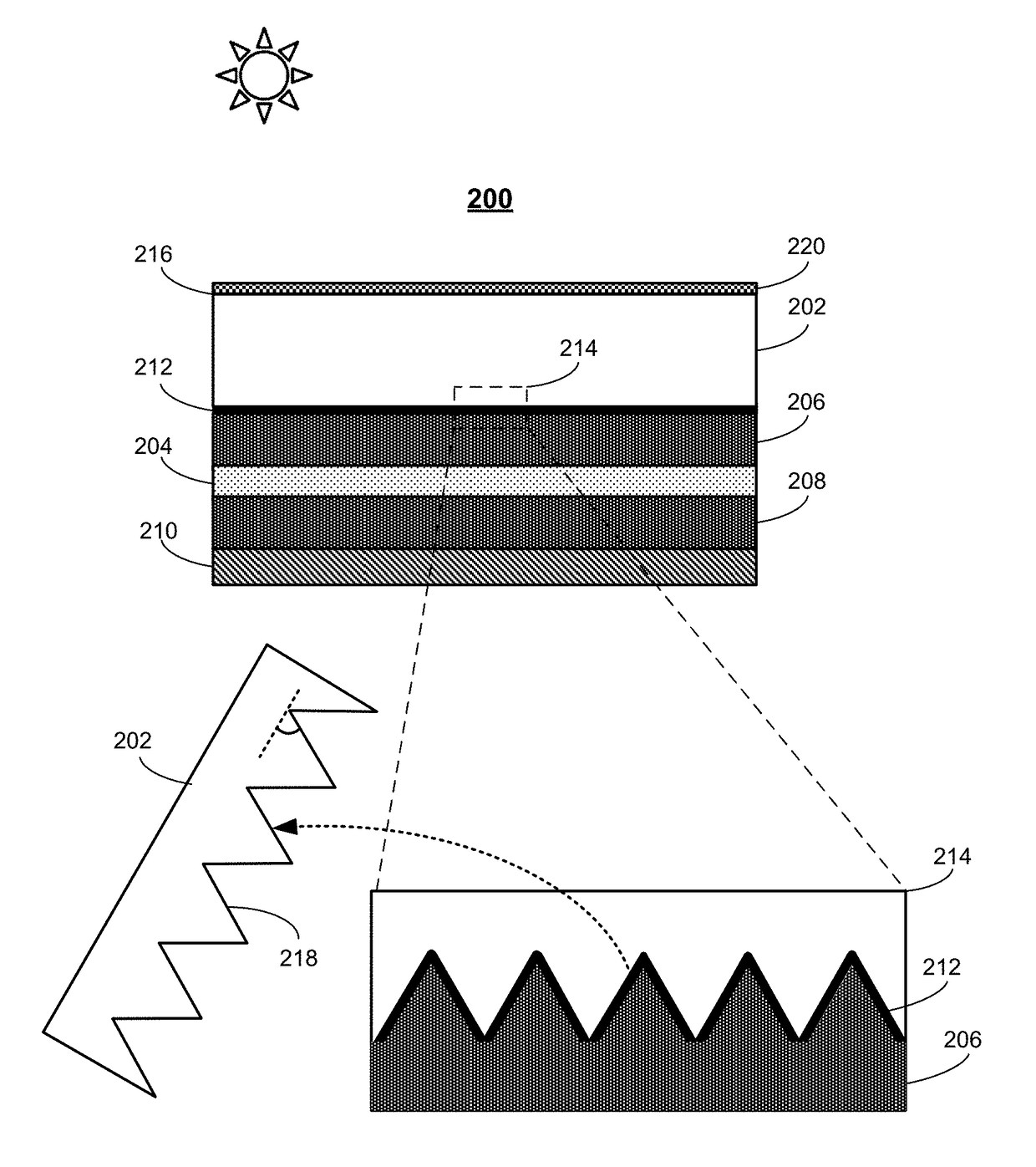
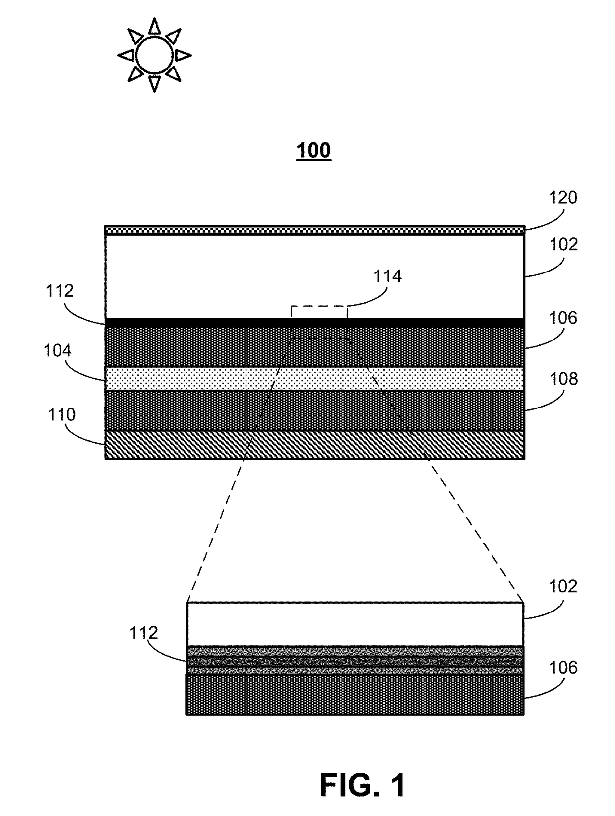
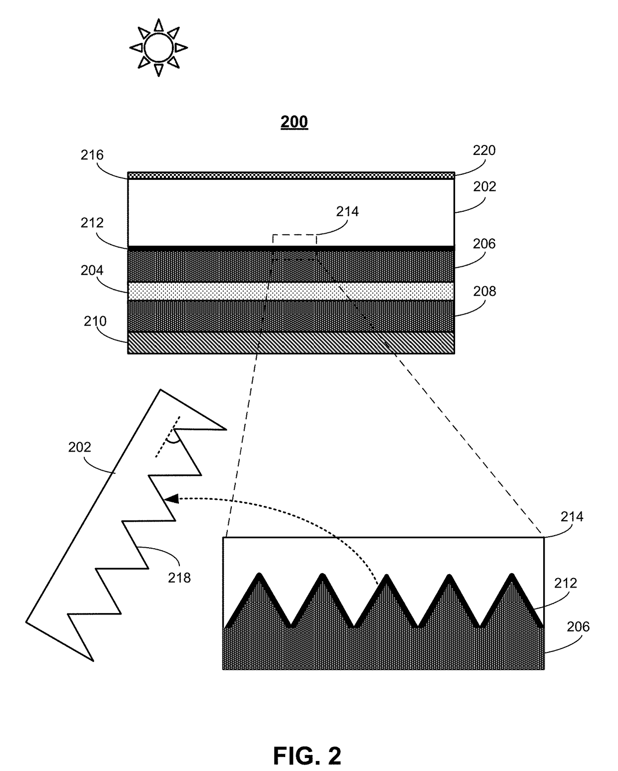
[0047]FIG. 1 presents a diagram illustrating a cross-sectional view of exemplary PV module 100 in accordance with one embodiment described herein. As can be seen in FIG. 1, PV module 100 includes transparent substrate 102, which is typically made of glass, array of solar cells 104, and top encapsulation sheet 106 and bottom encapsulation sheet 108, which are positioned on the front side and the back side of solar cells 104 to encapsulate solar cells 104. In some embodiments, encapsulation sheets 106 and 108 are made of a transparent material such as polyvinyl butyral (PVB), thermoplastic olefin (TPO), or ethylene vinyl acetate (EVA). However, encapsulation sheets 106 and 108 can be made of other conventional or newly-developed encapsulation materials. PV module 100 additionally includes a back-side cover layer 110 positioned on the back side of PV module 100 opposite to substrate 102.

[0048]Note that when PV module 100 is used to convert light to an e...


PUM


Abstract

A low-reflection-loss low-angle-sensitive colored photovoltaic (PV) module is described. This colored PV module includes a transparent substrate; an array of solar cells encapsulated between a top encapsulation sheet and a bottom encapsulation sheet; and a color filter structure embedded between the top encapsulation sheet and the transparent substrate and configured to cause wavelength-selective reflections of incident light received by the colored PV module. Moreover, the transparent substrate includes a flat front surface configured to receive the incident light and a texture back surface configured with an array of features. The color filter structure is formed on the textured back surface of the transparent substrate to create a textured interface between the textured back surface and the color filter structure.

Description

RELATED APPLICATION[0001]This application claims the benefit of U.S. Provisional Application No. 62 / 343,659, Attorney Docket Number P301-1PUS, entitled “MULTI-LAYER OPTICAL COATINGS ON TEXTURED GLASS AND ITS APPLICATION OF COLORED PV MODULES,” by inventors Yangsen Kang, Zhigang Xie, Jianhua Hu, and Zheng Xu, filed May 31, 2016, the disclosure of which is incorporated by reference herein.BACKGROUNDField[0002]This disclosure is generally related to the designs of photovoltaic (or “PV”) modules. More specifically, this disclosure is related to designs and fabrication of low-reflection-loss, low-angle-sensitive colored PV modules.Related Art[0003]Crystalline-silicon based solar cells have been shown to have superb energy conversion efficiency. While device design and fabrication techniques continue to mature, and with the price of crystalline silicon becoming progressively lower, solar panels are being offered at historical low prices. In addition, with newly available financing plans a...

Claims


Application Information

Patent Timeline
Patent Type & Authority Applications(United States)
IPC IPC(8): H01L31/0236H01L31/056H01L31/049H01L31/18H01L31/0216
CPCH01L31/02366H01L31/056H01L31/18H01L31/049H01L31/02168H01L31/02162H01L31/02H01L31/048Y02E10/52
Inventor KANG, YANGSENXIE, ZHIGANGHU, JIANHUAXU, ZHENG
Owner SOLARCITY
Learn More