Luminous keyboard

A technology of luminous keyboards and luminous components, which is applied to legends, electrical components, electric switches, etc., and can solve problems such as large angles, uneven luminous effects, and inability to perform total reflection

Inactive Publication Date: 2017-01-18
PRIMAX ELECTRONICS LTD
View PDF4 Cites 2 Cited by
  • Summary
  • Abstract
  • Description
  • Claims
  • Application Information

AI Technical Summary

Problems solved by technology

[0008] During the process of projecting the multiple light beams B onto the light guide plate 22, the multiple light beams B are emitted from the light emitting element 232 in the form of radiation, so that the angle at which some of the light beams B enter the light guide plate 22 is too large to perform total reflection.
The light beam B that cannot be totally reflected will pass through the light guide plate 22 and be projected upward, so a bright spot phenomenon (or bright band, bright area phenomenon) will occur near the light emitting element 232. The bright spot phenomenon is that the light beam is too concentrated and Causes a highly concentrated luminous effect, which will lead to uneven luminous effect of the luminous keyboard 2

Method used


Image

  • Luminous keyboard
  • Luminous keyboard
  • Luminous keyboard

Examples


Embodiment Construction

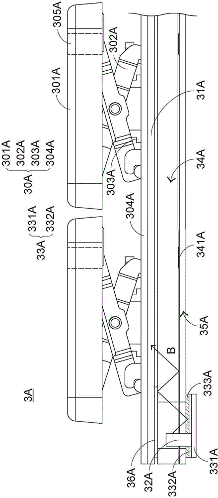
[0092] In view of the problems in the prior art, the present invention provides a light-emitting keyboard that can solve the problems in the prior art. First illustrate the structure of the luminous keyboard of the present invention, please refer to image 3 , which is a schematic cross-sectional view of the structure of the light-emitting keyboard in the first preferred embodiment of the present invention. The light-emitting keyboard 3A of the present invention includes a key module 30A, a support plate 31A, a plurality of light-emitting elements 32A (only one is shown in the figure), a light-emitting circuit board 33A, a light guide plate 34A, a reflection sheet 35A and a light-shielding sheet 36A. The key module 31A is exposed on the upper surface of the light-emitting keyboard 3A, and it includes a plurality of key caps 301A, a plurality of connecting elements 302A, a plurality of elastic elements 303A, and a switch circuit board 304A, and the key caps 301A, the connecting...


PUM


Abstract

The invention relates to a luminous keyboard, which comprises a key module, a plurality of luminous elements, a luminous circuit board and a light guide plate. The luminous circuit board is provided with a light control element which is arranged on a circuit board body or a protection layer and located between the light guide plate and the luminous elements. The luminous elements generate light beams, and the light beams are projected to the luminous circuit board. Reflection of the light beams is reduced through the light control element on the luminous circuit board. Therefore, the luminous keyboard provided by the invention can relieve a light spot phenomenon caused by excessive concentration of the light beams.

Description

technical field [0001] The invention relates to a keyboard, in particular to a luminous keyboard with a luminous function. Background technique [0002] Common computer peripheral input devices include a mouse, a keyboard, and a trackball. The keyboard can directly input text and symbols to the computer, so it is highly valued by users and input device manufacturers. [0003] see figure 1 , which is a schematic diagram of an appearance structure of an existing keyboard. There are a plurality of keys 10 on the surface of the existing keyboard 1, and the plurality of keys 10 are classified into general keys 101, number keys 102, and function keys 103, etc. The corresponding signal is given to the computer to make the computer perform the pressed key function. For example, the general key 101 is used to input symbols such as English letters, the number key 102 is used to input numbers, and the function key 103 is used to provide various functions, such as F1 ~F12 etc. Where...

Claims


Application Information

Patent Timeline
IPC IPC(8): H01H13/83
CPCH01H13/83H01H2219/054H01H2219/06H01H2219/062
Inventor 陈仲渊
Owner PRIMAX ELECTRONICS LTD
Why Eureka
Try Eureka