
Method for evaluating abrasive grains, and method for manufacturing silicon wafer

a technology of abrasive grains and manufacturing methods, which is applied in the direction of manufacturing tools, fine working devices, other chemical processes, etc., can solve the problems of deteriorating the cutting performance of wire saws and lowering the quality of silicon wafers, and achieves high-quality silicon wafers

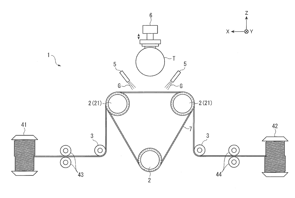
Active Publication Date: 2017-11-30
SUMCO CORP
View PDF2 Cites 0 Cited by
  • Summary
  • Abstract
  • Description
  • Claims
  • Application Information

AI Technical Summary

Benefits of technology

This patent relates to a method for evaluating abrasive grains used in the cutting of silicon ingots. The method involves sedimentation of the abrasive grains and the impurities present in the ingot slurry. By measuring the turbidity of the sedimented solution, the amount of impurities can be accurately measured and compared to the amount of impurities in the abrasive grains. This allows for a determination of the quality of the silicon wafer to be obtained prior to cutting. Additionally, the use of water or ultra-pure water as the solvent for the evaluation solution allows for faster sedimentation of the polishing grains and reduces the evaluation time. Shaking the polishing grains with impurities removed using various methods helps to obtain a more accurate measurement of the impurities and is particularly useful for high-quality silicon wafer production. The dilution step prevents the turbidity of the solution from exceeding the measurement range of the device. Overall, this method provides a reliable and efficient means for evaluating abrasive grains in the silicon ingot cutting process.

Problems solved by technology

When an ingot is cut using slurry containing the polishing grains as mentioned above, the impurities present between the polishing grains and the ingot may deteriorate the cutting performance of the wire saw to lower the quality of the silicon wafer.

Method used


Image

  • Method for evaluating abrasive grains, and method for manufacturing silicon wafer
  • Method for evaluating abrasive grains, and method for manufacturing silicon wafer
  • Method for evaluating abrasive grains, and method for manufacturing silicon wafer

Examples


experiment 1

[0065]Initially, as the unused abrasive grains used for ingot-cutting slurry, abrasive grains A1, A2 manufactured by A company, abrasive grains B1, B2 manufactured by B company, abrasive grains C manufactured by C company, and abrasive grains D manufactured by D company were prepared. The production lot of the abrasive grains A1 was different from the production lot of the abrasive grains A2. Similarly, the production lot of the abrasive grains B1 was different from the production lot of the abrasive grains B2. The particle size of each of the abrasive grains was #2000.

[0066]Next, 30 gram of the abrasive grains A1 were mixed with 70 ml of pure water (solvent) through a manual operation of an operator to prepare an evaluation solution A1. Further, evaluation solutions A2, B1, B2, C, D were prepared under the same conditions as those in preparing the evaluation solution A1 except that the abrasive grains A1 were changed respectively to abrasive grains A2, B1, B2, C, D.

[0067]Then, the ...

experiment 2

[0071]As described above, the turbidity of the supernatant of the evaluation solution sometimes cannot be appropriately measured using a turbidity meter. Accordingly, it was checked whether or not the turbidity of the supernatant became so small as to be within the measurement range of the turbidity meter by lengthening the stand-still time after preparing the evaluation solution.

[0072]After preparing the same evaluation solutions A1,A2,B1,B2,C, D as those prepared in the Experiment 1 and the evaluation solutions were left still for 3, 12 and 24 hours at a normal temperature, the turbidities of the supernatants of the evaluation solutions were measured using the above turbidity meter. The results are shown in FIG. 4. The turbidity was also visually checked.

[0073]It should be noted that, when the stand-still time exceeds 24 hours, it becomes difficult to manage the receipt and stock of the abrasive grains during mass production. Accordingly, the maximum value of the stand-still time ...

experiment 3

[0076]In view of the results of the Experiment 2, it was checked whether or not the amount of the impurities could be appropriately estimated using the turbidity meter by diluting the supernatant of the evaluation solution even when much amount of impurities were present in the abrasive grains.

[0077]After the evaluation solution A1 identical with that in the Experiment 1 was prepared in three colorimetric tubes and was left still for 3 hours at a normal temperature, the supernatants in the respective colorimetric tubes were diluted twofold, fivefold and tenfold with pure water. The turbidities of the diluted supernatants were measured using the above turbidity meter. Similarly, the turbidities of the supernatants of the evaluation solutions A2, B1, B2, C, D diluted twofold, fivefold and tenfold with pure water were measured using the turbidity meter. The results are shown in FIG. 5.

[0078]As shown in FIG. 5, when the solutions were diluted twofold with pure water, the measured values...


PUM


Abstract

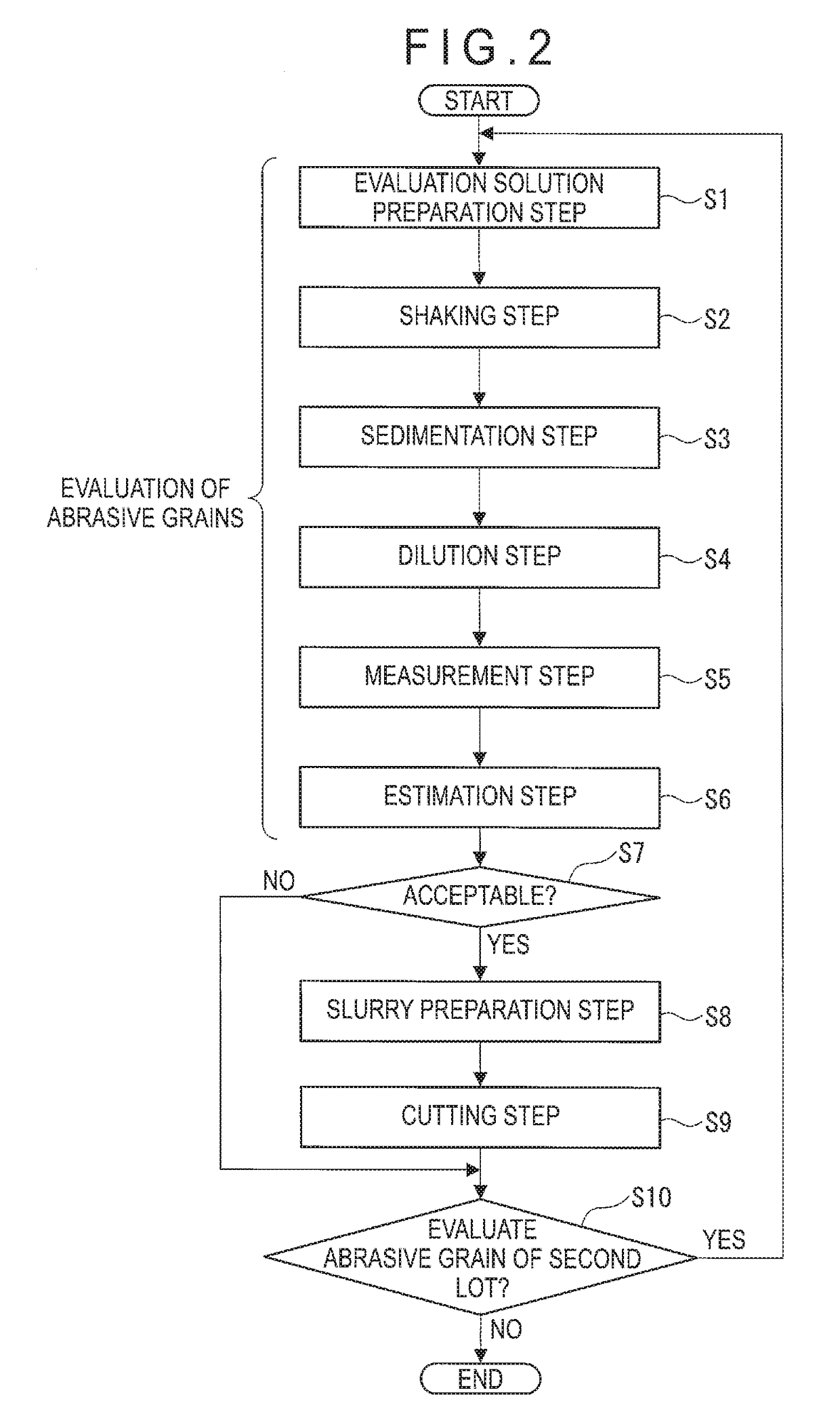
An evaluation method of abrasive grains used in an ingot-cutting slurry includes: an evaluation solution preparation step in which abrasive grains including polishing grains and impurities are dissolved in a solvent to prepare an evaluation solution; a sedimentation step in which a container containing the evaluation solution is left still to settle the polishing grains; a measurement step in which a turbidity of supernatant of the evaluation solution is measured using the measurement device; and an estimation step in which an amount of the impurities is estimated based on the measurement result of the turbidity of the supernatant.

Description

TECHNICAL FIELD[0001]The present invention relates to an evaluation hod of abrasive grains and a manufacturing method of a silicon wafer.BACKGROUND ART[0002]Methods for manufacturing silicon wafers from a silicon monocrystal ingot have been known (see, for instance, Patent Literature 1).[0003]According to the method disclosed in Patent Literature 1, a silicon ingot is pressed against a wire in motion while slurry containing polishing grains having a mean particle diameter ranging from 13 μm to 15 μm is supplied to the wire, thereby cutting the silicon ingot and manufacturing silicon wafers.CITATION LISTPatent Literature(s)[0004]Patent Literature 1 JP-10-52816 ASUMMARY OF THE INVENTIONProblem(s) to be Solved by the Invention[0005]However, the polishing grains used in the method disclosed in Patent Literature 1 contain impurities such as FC (Free Carbon) having a diameter of 3 μm or less not contributing to enhancement in cutting performance, as well as polishing grains such as GC (Gr...

Claims


Application Information

Patent Timeline
IPC IPC(8): G01N33/40G01N21/49G01N15/06C09K3/14B24B57/02H01L21/304B24B27/06
CPCG01N33/40G01N21/49G01N15/06B24B27/06H01L21/304B24B57/02C09K3/14G01N2015/0053G01N21/51G01N21/94B28D5/007G01N21/85Y02P70/10
Inventor MINAMIHATA, YUUJI
Owner SUMCO CORP
Learn More