
Soundproof structure and soundproof structure manufacturing method

Active Publication Date: 2017-11-30
FUJIFILM CORP
View PDF11 Cites 9 Cited by
  • Summary
  • Abstract
  • Description
  • Claims
  • Application Information

AI Technical Summary

Benefits of technology

The present invention aims to provide a soundproof structure that is light and thin, with high robustness and stability. It has excellent air permeability, allowing wind and heat to pass through, but no heat inside. This structure is suitable for use in equipment, automobiles, and household applications. It is also easy to manufacture. The technical effect of the invention is that sound insulation characteristics are not affected by the position or shape of holes, which increases manufacturing stability.

Problems solved by technology

However, there has been a problem that the range of selection of a sound absorbing material is narrow and accordingly it is difficult to achieve the high sound absorption effect in a low frequency region.
Since the sound absorbing material of such a sound absorber completely blocks the through-hole of the frame body, the sound absorbing material does not allow the wind or heat to pass therethrough and accordingly the heat tends to be caught thereinside.
Therefore, there has been a problem that this is not suitable for the sound insulation of equipment and automobiles, which is disclosed in JP4832245B in particular.
For this reason, it has been difficult to effectively use the sound absorber in general equipment and automobiles in which specific frequency components, such as motor sounds, are often strongly generated in a pulsed manner.
However, as a lighter and thinner sound insulation structure required in equipment, automobiles, general households, and the like, there are the following problems.

Method used

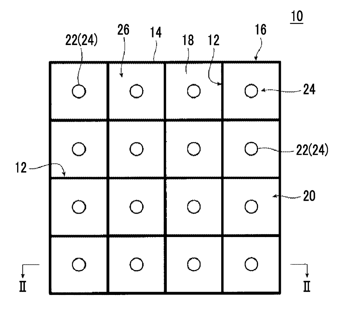
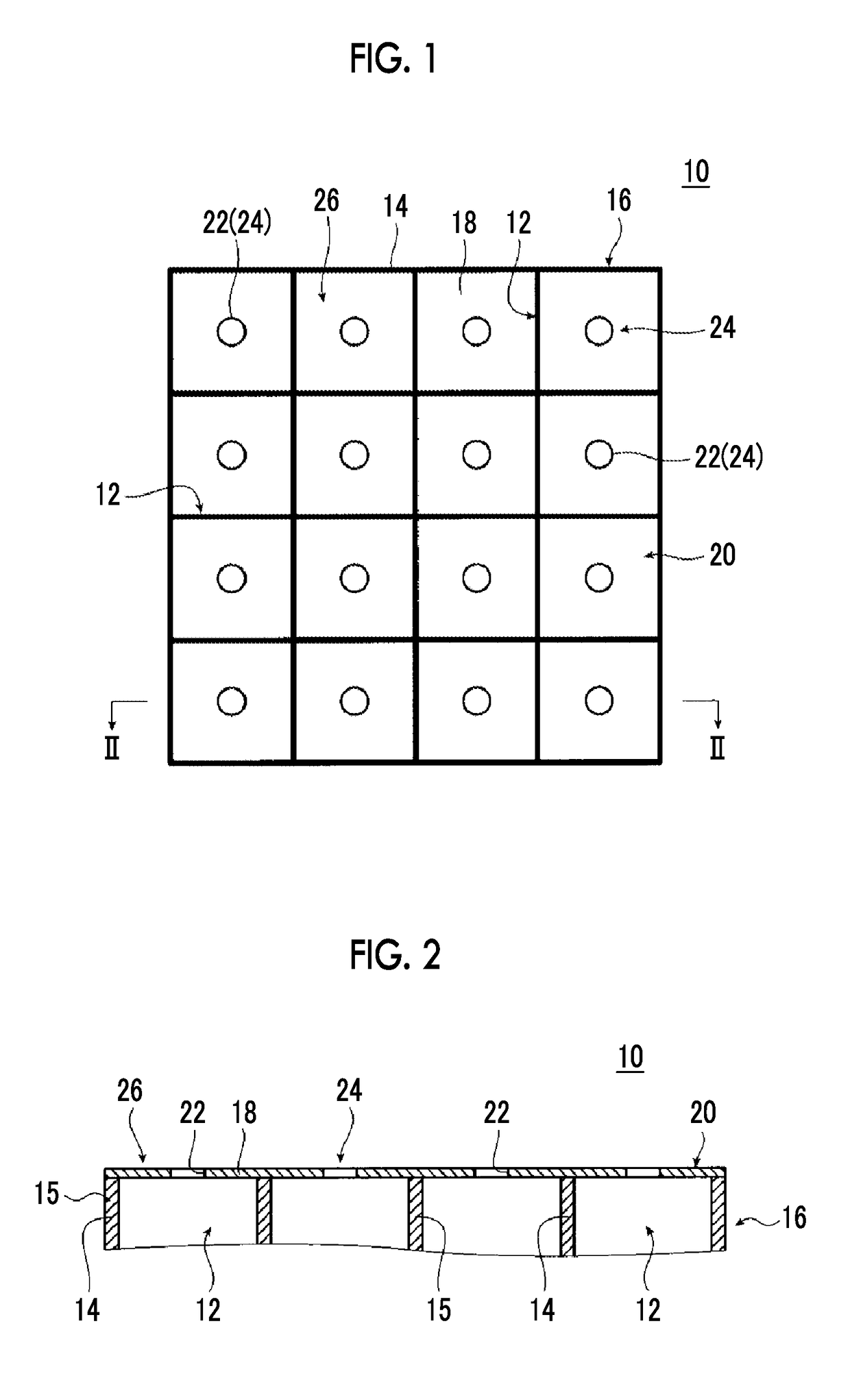
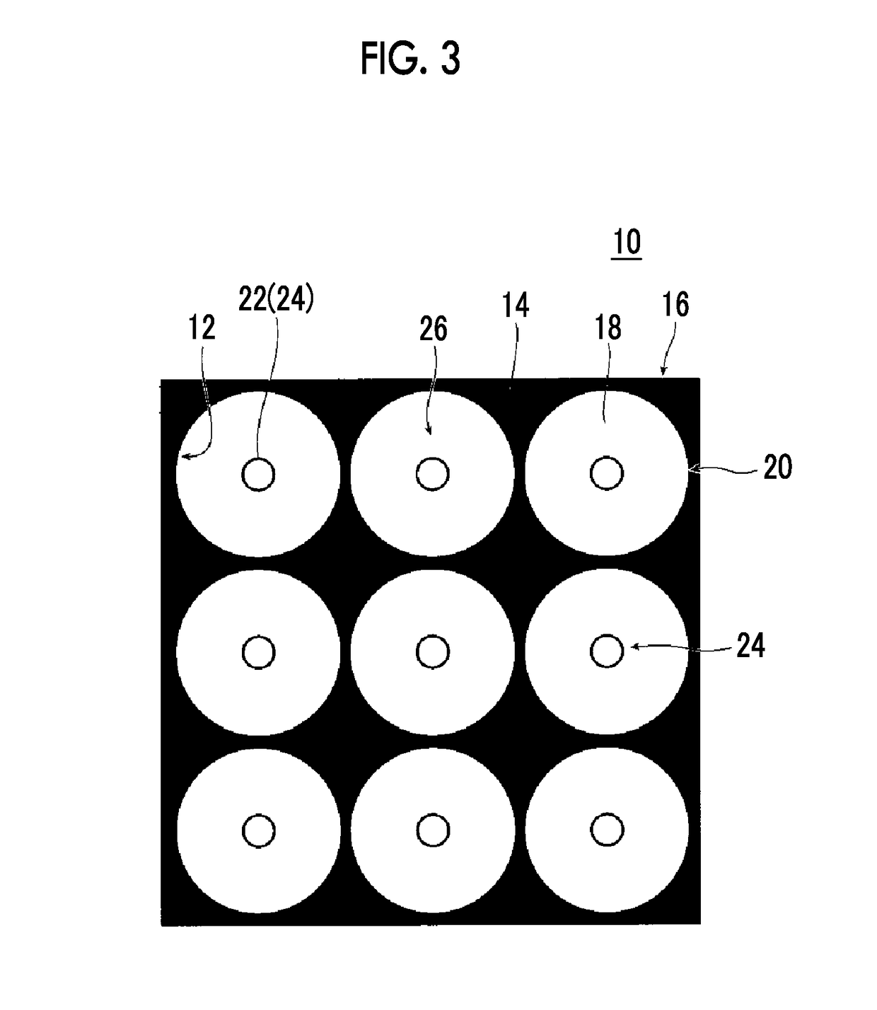

Image

  • Soundproof structure and soundproof structure manufacturing method
  • Soundproof structure and soundproof structure manufacturing method
  • Soundproof structure and soundproof structure manufacturing method

Examples


example 1

[0184]Hereinafter, a method of manufacturing a soundproof structure of Example 1 having the hole 22 with a diameter of 200 μm (=200×10−6 m) is shown in which the PET film thickness of the film 18 is 50 μm (=50×10−6 m) and the size of the frame 14 is 7.5 mm (=7.5 x×10−3 m).

[0185]A PET film Lumirror manufactured by Toray Industries, Inc.) 50 μm product was used as the film 18. An aluminum having a thickness of 3 mm and a width of 3 mm was used as the frame 14, and the shape of the frame 14 was a square. Processing was performed with one side of the square through-hole 12 as 7.5 mm. The frame structure has a total of 225 (15×15) through-holes 12. The frame structure was fixed to the PET film with an adhesive. As a result, a frame•film structure configured to include the frame 14 and the film 18 was manufactured.

[0186]A step of drilling the hole 22 in the film 18 of the frame•film structure was performed as follows.

[0187]First, a black spot intended for light absorption was drawn on the...

examples 2 to 7

[0199]A frame-film structure was prepared in the same manner as in Example 1. Since it is known that the amount of heat generated can be changed by changing the laser irradiation time and accordingly the size of the hole 22 can be changed, the desired hole 22 of 20 μm 2000 μm was able to be obtained on the PET film by optimizing the laser irradiation time and power. Table 3 shows the results obtained in this manner that include a shielding frequency in the soundproof structure of each example. The sound insulation characteristic of Example 5 is shown by the dotted line in FIG. 10.

example 8

[0200]After manufacturing a frame-film structure in the same manner as in Example 1, the hole 22 was physically formed by sticking a needle into the film instead of forming the hole 22 by laser irradiation. By adjusting the force, it was possible to obtain the hole 22 with a diameter of 200 μm. The shielding spectrum (transmission loss) of Example 8 obtained in this manner was obtained with no change from that of Example 1. The results are shown in Table 3.


PUM

PropertyMeasurementUnit
Fractionaaaaaaaaaa
Sizeaaaaaaaaaa
Frequencyaaaaaaaaaa

Abstract

A soundproof structure has one or more soundproof cells. Each of the one or more soundproof cells includes a frame having a through-hole, a film fixed to the frame, and an opening portion configured to include one or more holes drilled in the film. Neither end portions of the through-hole of the frame are closed. The soundproof structure has a shielding peak frequency, which is determined by the opening portion of each of the one or more soundproof cells and at which a transmission loss is maximized, on a lower frequency side than a first natural vibration frequency of the film of each of the one or more soundproof cells, and selectively insulates sound in a predetermined frequency band including the shielding peak frequency at its center. Accordingly, there is provided a soundproof structure that is light and thin, does not depend on the position and shape of a hole, has high robustness as a sound insulation material, is stable, has air permeability, has no heat, and is excellent in manufacturability, and a soundproof structure manufacturing method.

Description

CROSS REFERENCE TO RELATED APPLICATIONS[0001]This application is a continuation application of International Application No. PCT / JP2016 / 055904 filed on Feb. 26, 2016, which claims priority under 35 U.S.C. 119(a) to Japanese Patent Application No. 2015-039513 filed on Feb. 27, 2015 and Japanese Patent Application No. 2015-121994 filed on Jun. 17, 2015. Each of the applications hereby expressly incorporated by reference into the present application.BACKGROUND OF THE INVENTION1. Field of the Invention[0002]The present invention relates to a soundproof structure and a soundproof structure manufacturing method, and more particularly to a soundproof structure that is formed by one soundproof cell, which includes a frame, a film fixed to the frame, and an opening portion including one or more holes drilled in the film, or formed by arranging a plurality of soundproof cells in a two-dimensional manner and that is for strongly shielding the sound of a target frequency selectively, and a soun...

Claims


Application Information

Patent Timeline
IPC IPC(8): B23K26/382G10K11/16E04B1/86
CPCB23K26/382G10K11/16E04B1/86G10K11/162G10K11/172B23K26/00
Inventor HAKUTA, SHINYAYAMAZOE, SHOGOYOSHIHIRO, TATSUYAOHTSU, AKIHIKOKASAMATSU, TADASHINAYA, MASAYUKI
Owner FUJIFILM CORP
Learn More