
System And Selecting Method For Flexible Allocations Of Antenna Sub-Arrays In Multiple Input Multiple Output Systems

Active Publication Date: 2017-11-16
NAT TAIWAN UNIV +1
View PDF4 Cites 19 Cited by
  • Summary
  • Abstract
  • Description
  • Claims
  • Application Information

AI Technical Summary

Benefits of technology

The patent describes a circuit that can choose between multiple antennae to improve efficiency and directivity. This circuit has the benefits of being easy to use and achieving high power and low complexity.

Problems solved by technology

Nevertheless, transmissions in the mmWave radio channel may suffer from serious power path losses.
However, in an mmWave radio system, the antennas are in close proximity to each other, due to the short wavelength.
Further, when a digital beamforming architecture or a precoding technique is applied to the large antenna arrays of a mmWave radio system, the beamformer itself may result in problems of high cost and high power consumption.
Thus, full digital beamforming with the uses of DAC / ADC will dramatically increase the power consumption and cost of the beamforming architecture.
Moreover, the channel capacity gain may not increase proportionately with the number of antennas.
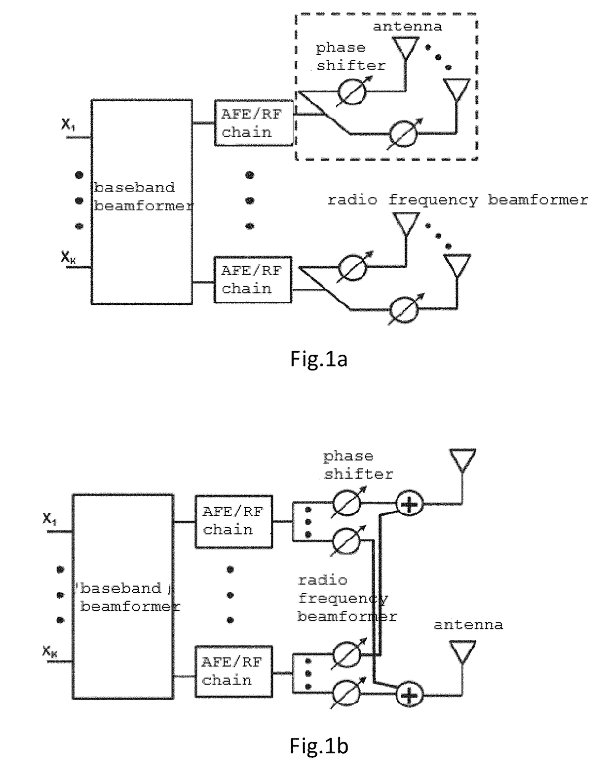
In contrast, the partially connected hybrid beamforming architecture has the advantage of a lower cost, while also have the disadvantage of wider beams and lower array gains.

Method used


Image

  • System And Selecting Method For Flexible Allocations Of Antenna Sub-Arrays In Multiple Input Multiple Output Systems
  • System And Selecting Method For Flexible Allocations Of Antenna Sub-Arrays In Multiple Input Multiple Output Systems
  • System And Selecting Method For Flexible Allocations Of Antenna Sub-Arrays In Multiple Input Multiple Output Systems

Examples


Embodiment Construction

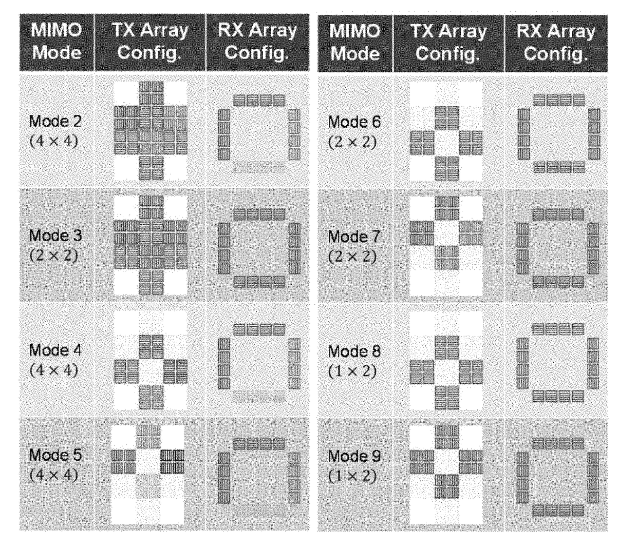
[0028]The present invention relates to a multiple-input multiple-output (MIMO) technology. The MIMO technology adopts multiple antennas at the transmitting end or the receiving end for improving transmission efficiency.

[0029]The MIMO technology may increase system throughput and transmission reliability without increasing the required bandwidth and output power. In a MIMO system, the transmission energy can be distributed to different antennas for transmission signal, it can enhance the spectrum efficiency (bits per second per hertz). Moreover, the same signal can be received via different channels simultaneously in the MIMO system, thus reducing the channel fading effect.

[0030]Precoding is one of the practical techniques for the MIMO system. Precoding is a multi-stream beamforming technique. Beamforming is a signal processing technique, which processes signals with matrix operation before transmitting or receiving by the less noisy channels. In other words, precoding technique is a...


PUM


Abstract

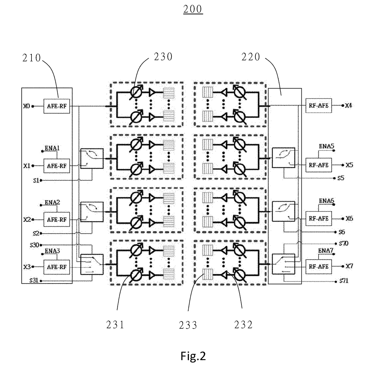
The invention provides a selection circuit and method of multiple input / output ports and antenna sub-arrays for reconfigurable hybrid beamforming. The selection circuit includes a plurality of digital signal processing modules, each electrically connected to a respective input / output port, a plurality of analog front end (AFE) and radio frequency (RF) chains, each electrically connected to a respective digital signal processing module, a plurality of multiplexing circuits, each electrically connected to any number of the AFE and RF chains, and a plurality of antenna sub-arrays, each electrically connected to a respective multiplexing circuit, wherein the multiplexing circuits set any number of the antenna sub-arrays to transmit / receive any number of electrical signals of input / output ports transmitted by the AFE and RF chains. The invention further provides a signal processing and transmission / reception system and a combination selection method of multiple input / output ports and antenna sub-arrays based on the selection circuit.

Description

CROSS-REFERENCE TO RELATED APPLICATIONS[0001]This Non-provisional application claims priority under 35 U.S.C. §119(a) on Patent Application No. 62 / 335,185 filed in US May 12, 2016, the entire contents of which are hereby incorporated by reference.FIELD OF THE INVENTION[0002]The present invention relates to a selection circuit and method of multiple input / output ports and antenna sub-arrays for reconfigurable hybrid beamforming. More particularly, the selection circuit of the present invention performs signal transmission between the transmission end and the reception end of multiple input multiple output (MIMO) system and finds a preferable multiple input / output port and antenna sub-array combination configuration.BACKGROUND OF THE INVENTION[0003]In millimeter wave (mmWave) radio channels, a wide and continuous frequency bandwidth can be available, so that the data transmission rate in this frequency band can be substantially increased. Nevertheless, transmissions in the mmWave radi...

Claims


Application Information

Patent Timeline
IPC IPC(8): H04B7/0417H04B7/08H04B7/06H04L27/00
CPCH04B7/0417H04L27/0002H04B7/0626H04B7/086H04B7/0617H04B7/0469H04L25/03343H04L25/03898H04L25/0204
Inventor WU, SAU-HSUAN
Owner NAT TAIWAN UNIV
Learn More