
Unmanned aerial vehicle and propeller

A technology of propellers and unmanned aerial vehicles, applied in the field of aircraft, can solve the personal safety threats of operators and nearby people, reduce the actual output of propellers 100, and the large size of unmanned aerial vehicles, etc., to achieve portable design, reduce safety hazards, reduce The effect of overall thickness

Pending Publication Date: 2017-06-13
ELANVIEW TECHNOLOGY CO LTD
View PDF8 Cites 0 Cited by
  • Summary
  • Abstract
  • Description
  • Claims
  • Application Information

AI Technical Summary

Problems solved by technology

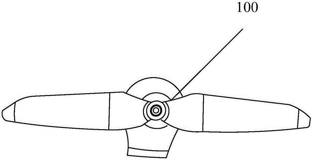
[0003] Existing unmanned aerial vehicle body size is all bigger, and its propeller 100 is generally exposed outside, as figure 1 As shown, due to its high-speed operation, it may pose a potential threat to the personal safety of the operator and nearby people.
Moreover, existing unmanned aerial vehicles rely entirely on the rotation of the propeller 100 to provide lift. Due to the high-pressure downwash airflow generated by the relative motion between the propeller 100 and the air, it flows back to the top of the low-pressure propeller 100 outside the coverage of the propeller 100, and then re-enters the high-pressure downwash. Washing air flow forms a vortex ring, which reduces the actual output of the propeller 100, resulting in loss of lift

Method used


Image

  • Unmanned aerial vehicle and propeller
  • Unmanned aerial vehicle and propeller
  • Unmanned aerial vehicle and propeller

Examples


Embodiment Construction

[0020] In order to make the objectives, technical solutions, and advantages of the present invention clearer, the various embodiments of the present invention will be described in detail below with reference to the accompanying drawings. However, those of ordinary skill in the art can understand that, in each embodiment of the present invention, many technical details are proposed for the reader to better understand the present application. However, even without these technical details and various changes and modifications based on the following embodiments, the technical solution claimed in this application can be realized.

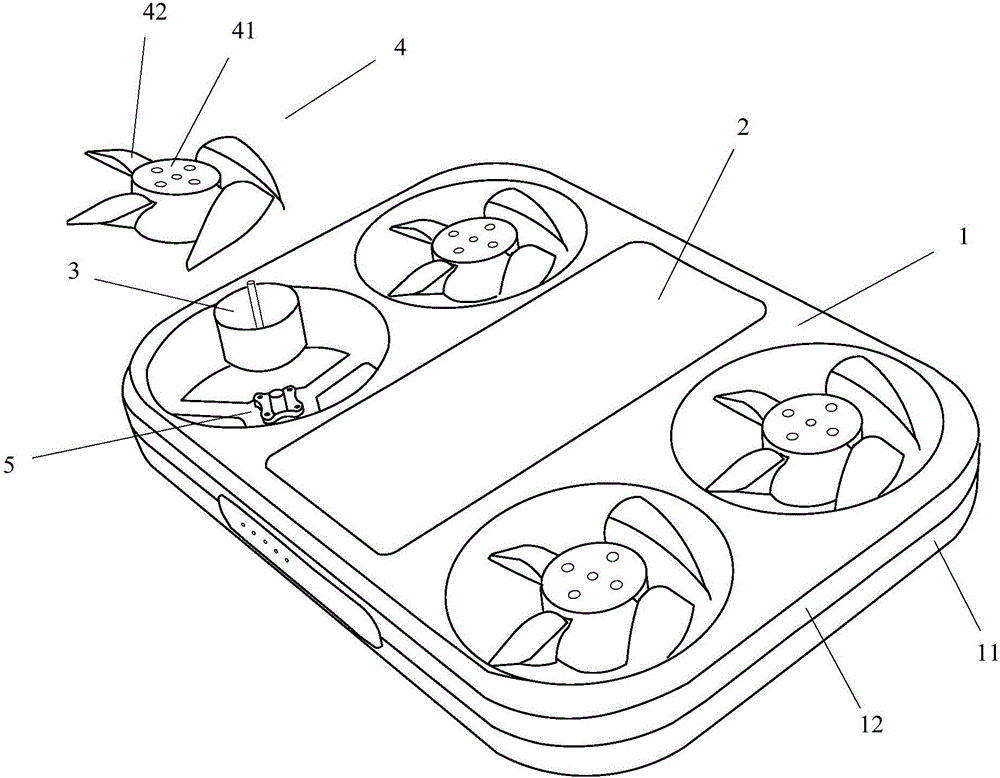
[0021] The first embodiment of the present invention relates to a drone, such as figure 2 Shown, including: body 1, controller 2, motor 3 and propeller 4

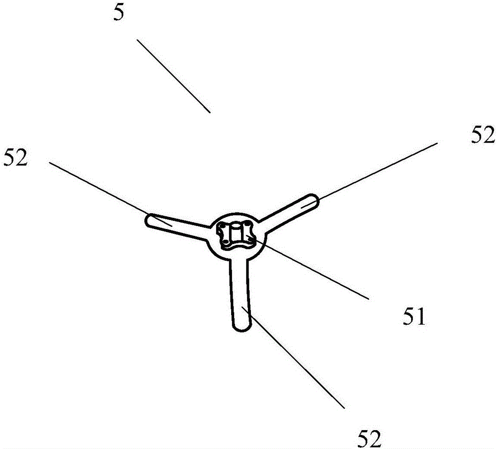
[0022] The body 1 has a circular through hole in the middle; a bracket 5 is provided in the through hole to support the propeller 4, and the propeller 4 is located in the through hole. The propeller 4 in...


PUM


Abstract

The invention relates to the field of air vehicles and discloses an unmanned aerial vehicle and a propeller. The unmanned aerial vehicle comprises an unmanned aerial vehicle body, a controller, motors and the propellers; circular through holes are formed in the middle of the unmanned aerial vehicle body; brackets are arranged in the through holes and used for supporting the propellers; the propellers are positioned in the through holes; and each propeller comprises a propeller hoop and propeller blades, which are connected with the propeller hoop; openings are formed in the bottoms of the propeller hoops to form accommodating chambers used for the motors to be accommodated; the propeller hoops are driven by the rotations of the motors to rotate; and the controller is electrically connected with the motors and used for controlling the motors. The embodiment of the invention further provides the propeller. Compared with the prior art, the propeller has the advantages that potential safety hazards can be reduced while the power effect of the unmanned aerial vehicle can be improved, the integral thickness of the unmanned aerial vehicle body can be also reduced, and the propeller is beneficial for light and portable design of the unmanned aerial vehicle.

Description

Technical field [0001] The present invention relates to the field of aircraft, in particular to unmanned aerial vehicles and propellers. Background technique [0002] UAVs are unmanned aircraft operated by radio remote control equipment and self-provided program control devices. They have been widely used in military and civilian fields. Because of its simple control and high reliability, it can take off and land vertically without a runway, and can hover in the air after take-off, so it has been widely used in various fields. [0003] Existing drones are large in size, and their propellers 100 are generally exposed, such as figure 1 As shown, due to its high-speed operation, this may pose a potential threat to the personal safety of operators and nearby people. Moreover, the existing drones completely rely on the rotation of the propeller 100 to provide lift. Due to the high-pressure downwash generated by the relative motion of the propeller 100 with the air, it flows back to the...

Claims


Application Information

Patent Timeline
Patent Type & Authority Applications(China)
IPC IPC(8): B64C27/08B64C27/32B64D27/24
CPCB64C27/08B64C27/32B64D27/24B64U10/10Y02T50/60
Inventor 刘锦涛薄澜李志明
Owner ELANVIEW TECHNOLOGY CO LTD
Learn More