Eureka AIR delivers breakthrough ideas for toughest innovation challenges, trusted by R&D personnel around the world.

Sensor for determining at least one parameter of a fluid medium flowing through a measurement channel

a technology of fluid medium and measurement channel, which is applied in the direction of engine testing, structural/machine measurement, instruments, etc., can solve the problems of reducing limiting the striving for precise flow topology, and affecting the accuracy of flow topology, so as to reduce dust contamination, reduce the drift of characteristic curves of sensors over their lifetime, and improve the resistance to disturbance

Active Publication Date: 2017-11-16
ROBERT BOSCH GMBH
View PDF6 Cites 12 Cited by
  • Summary
  • Abstract
  • Description
  • Claims
  • Application Information

AI Technical Summary

Benefits of technology

The present invention provides a sensor that has a reduced amount of dust contamination and is more resistant to electrostatic discharges. This is achieved by a sensor chip that is protected from dust particles on its surface. The sensor is mounted on a circuit board, which simplifies the manufacturing process and reduces the space requirement of the electronics module. The circuit board is connected to the sensor chip through electrical connections, which are protected from the fluid medium by a cover. The invention also provides an electrically conductive electronics compartment cover, which serves as a shielded space to protect the circuit boards from outside influences and allows for alternative ground potential. The sensor can be produced at low cost with low production-related outlay.

Problems solved by technology

A contamination of the sensor chip, and in particular of the micromechanical sensor membrane, for example with adherent dust particles, causes a change in the thermal economy, and thus causes deviations from characteristic curves.
However, there are limits on the striving for a precise tailoring of the flow topology, as well as on the limitation of fluctuations, in particular of the measurement-relevant draw-in area upstream from the micromechanical sensor system.
Such a contamination can cause, inter alia, characteristic curve drift.
Therefore, contamination of the micromechanical measurement element is possible in the entire mass flow region.
In this way, dust particles can in particular deposit on the sensor chip and on the micromechanical sensor membrane, and can cause, inter alia, a characteristic curve drift.
However, over the lifespan of the components, these adhesions of particles, caused for example electrostatically, accumulate and cause the described characteristic curve deviation.

Method used


Image

  • Sensor for determining at least one parameter of a fluid medium flowing through a measurement channel
  • Sensor for determining at least one parameter of a fluid medium flowing through a measurement channel
  • Sensor for determining at least one parameter of a fluid medium flowing through a measurement channel

Examples


Embodiment Construction

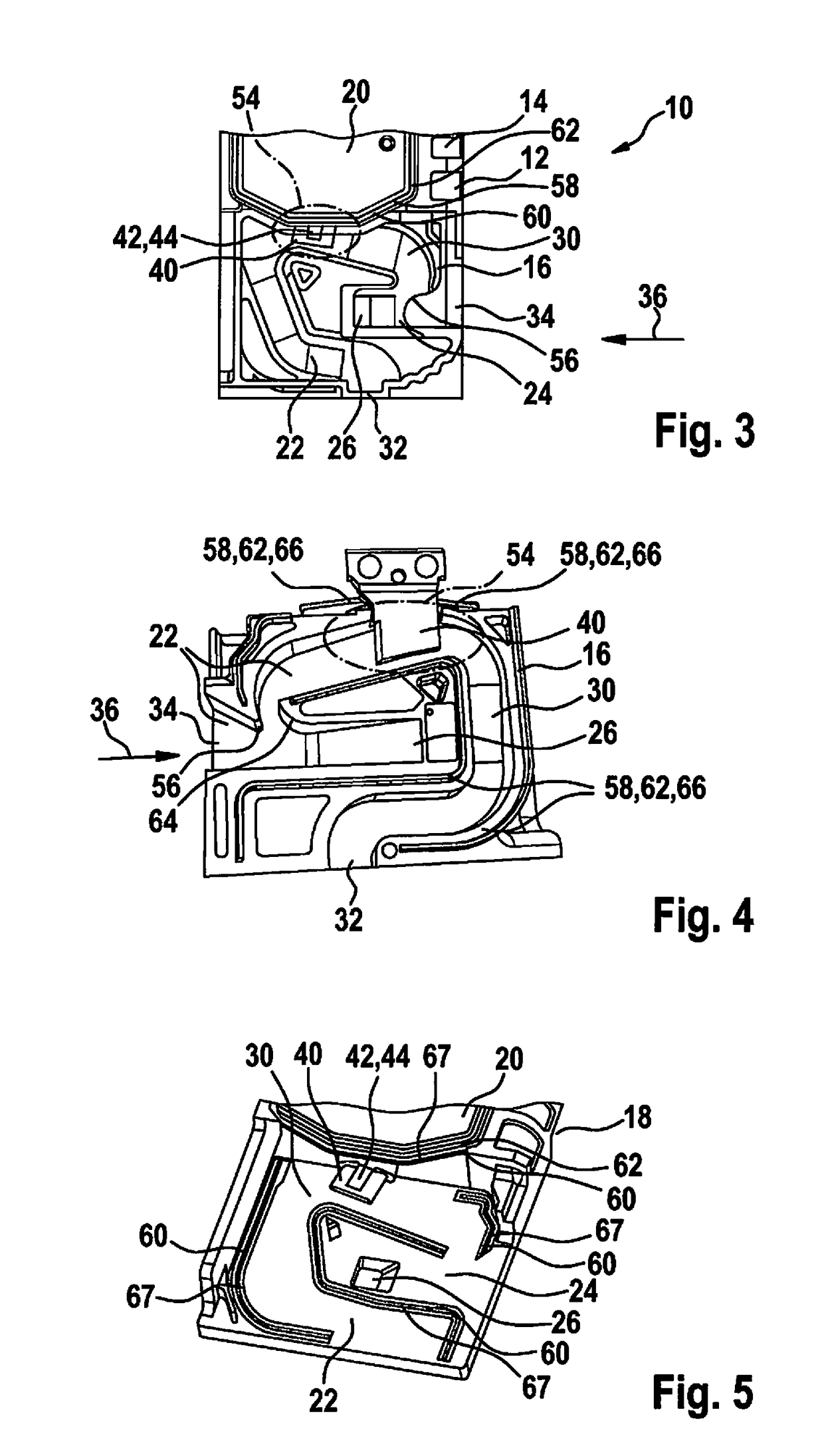
[0055]FIG. 1 shows a perspective view of a sensor system 10 for determining a parameter of the fluid medium. Sensor system 10 is fashioned as a hot-film air mass sensor and includes a sensor housing 12 fashioned as a plug-in sensor, which can be plugged for example into a flow tube, in particular an intake tract of an internal combustion engine. Sensor housing 12 has a housing body 14, a measurement channel cover 16, an electronics compartment 18, and an electronics compartment cover 24 sealing electronics compartment 18. A channel structure 22 is fashioned in housing body 16. Channel structure 22 has a main channel 24 that opens into a main flow outlet 26 on lower side 30, relative to the representation shown in FIG. 1 of sensor housing 12, as well as a bypass or measurement channel 30 branching off from main channel 24, which bypass channel opens into a bypass or measurement channel outlet 32, also situated on lower side 30 of sensor housing 12. A representative quantity of the fl...


PUM


Abstract

A sensor is provided for determining at least one parameter of a fluid medium flowing through a measurement channel, in particular an intake air mass flow of an internal combustion engine. The sensor has a sensor housing, in particular a plug-in sensor that is inserted into or is insertable into a flow tube, in which sensor a measurement channel is fashioned, and has at least one sensor chip situated in the measurement channel for determining the parameter of the fluid medium. The sensor housing has an electronics compartment for accommodating an electronics module and has an electronics compartment cover for closing the electronics compartment. The electronics compartment cover has, at least in part, electrically conductive properties. For example, the electronics compartment cover is placed onto the electrical ground of the sensor and, viewed in projection, partly or completely covers the sensor chip.

Description

BACKGROUND INFORMATION[0001]There are numerous, conventional methods and devices for determining a flow characteristic of fluid media, i.e. liquids and / or gases. The flow characteristics can be generally any physical and / or chemically measurable characteristics that qualify or quantify a flow of the fluid medium. In particular, this can be a flow speed and / or a mass flow and / or a volume flow.[0002]Below, the present invention is described in particular with reference to so-called hot-film air mass sensors, as described for example in Konrad Reif (pub.): Sensoren im Kraftfahrzeug [Sensors in the Motor Vehicle], 1st edition 2010, pp. 146-148. Such hot-film air mass sensors are generally based on a sensor chip, in particular a silicon sensor chip, having a sensor membrane as measurement surface or sensor area over which the flowing fluid medium can flow. Generally, the sensor chip includes at least one heating element, as well as at least two temperature sensors that are situated for e...

Claims


Application Information

Patent Timeline
Patent Type & Authority Applications(United States)
IPC IPC(8): G01F1/684G01F5/00G01M15/04
CPCG01F1/6845G01F1/6842G01F5/00G01M15/042
Inventor BRIESE, ACHIMMARKOV, ALEXANDERHAAG, AXEL-WERNERSOMMER, EDDABEYRICH, HANSKONZELMANN, UWEBODENBERGER, BASTIANSTEUBER, FRANKHUEFTLE, GERHARDUNGER, HOLGERRITTMANN, MICHAELEPPLER, MICHAELHERRMANN, REINHOLDSCHWARTZKOPFF, THOMAS
Owner ROBERT BOSCH GMBH
Why Eureka
Eureka Blog
Learn More