
Bearing component & method

a technology of bearing components and components, applied in the direction of shafts, bearings, rotary machine parts, etc., can solve the problems of high hardness and brittleness of white layers, cracks may develop in white layers between, and flaking, so as to improve rolling contact fatigue performan

Active Publication Date: 2017-11-16
AB SKF
View PDF0 Cites 4 Cited by
  • Summary
  • Abstract
  • Description
  • Claims
  • Application Information

AI Technical Summary

Benefits of technology

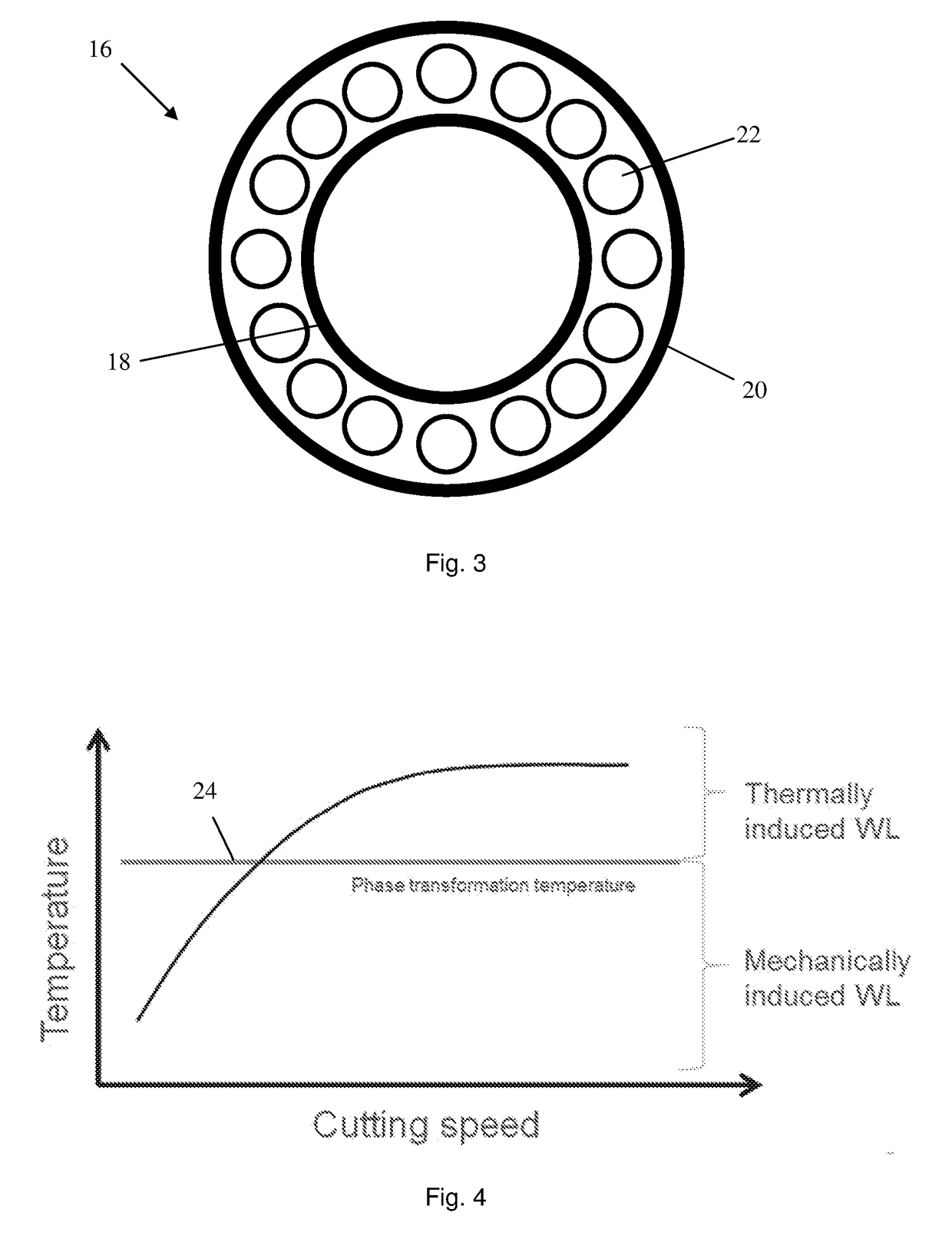
The invention provides an improved rolling contact fatigue performance of a bearing component that has been subjected to a hard machining process. This is achieved by limiting the temperature of the surface of the component to below the critical austenitization temperature, resulting in a predominantly mechanically-induced white layer with improved fatigue-resistance, higher fracture toughness, and / or increased wear resistance compared to a thermally-induced white layer.

Problems solved by technology

A significant limitation of the widespread use of hard machining of metallic materials is the so-called “white layer” effect, which is a microscopic alteration of the as-machined surface of a workpiece which appears white under a Light Optical Microscope (LOM), which effect is produced in response to an extremely high thermo-mechanical load exerted at the as-machined surface of a workpiece by the cutting tool.
Such white layers have a high hardness and are brittle compared to the bulk material of the workpiece.
When high external loads are applied on such a triple-layered structure (i.e. a hard or very hard white layer, a soft dark layer and hard unaffected material) cracks may develop in the white layer between the white layer and the dark layer, or between the dark layer and unaffected material.
When these cracks extend and connect together, flaking can occur.
A thermo-mechanically-affected workpiece surface comprising an etching-resistant white layer has conventionally been undesired because of high tensile and surface stresses associated therewith, such as reduced fatigue-resistance, lower fracture toughness, and / or reduced wear resistance of parts produced.
The white layer (10) is generally a hard phase and leads to the surface becoming brittle causing crack permeation and product failure.

Method used


Image

  • Bearing component & method
  • Bearing component & method
  • Bearing component & method

Examples


Embodiment Construction

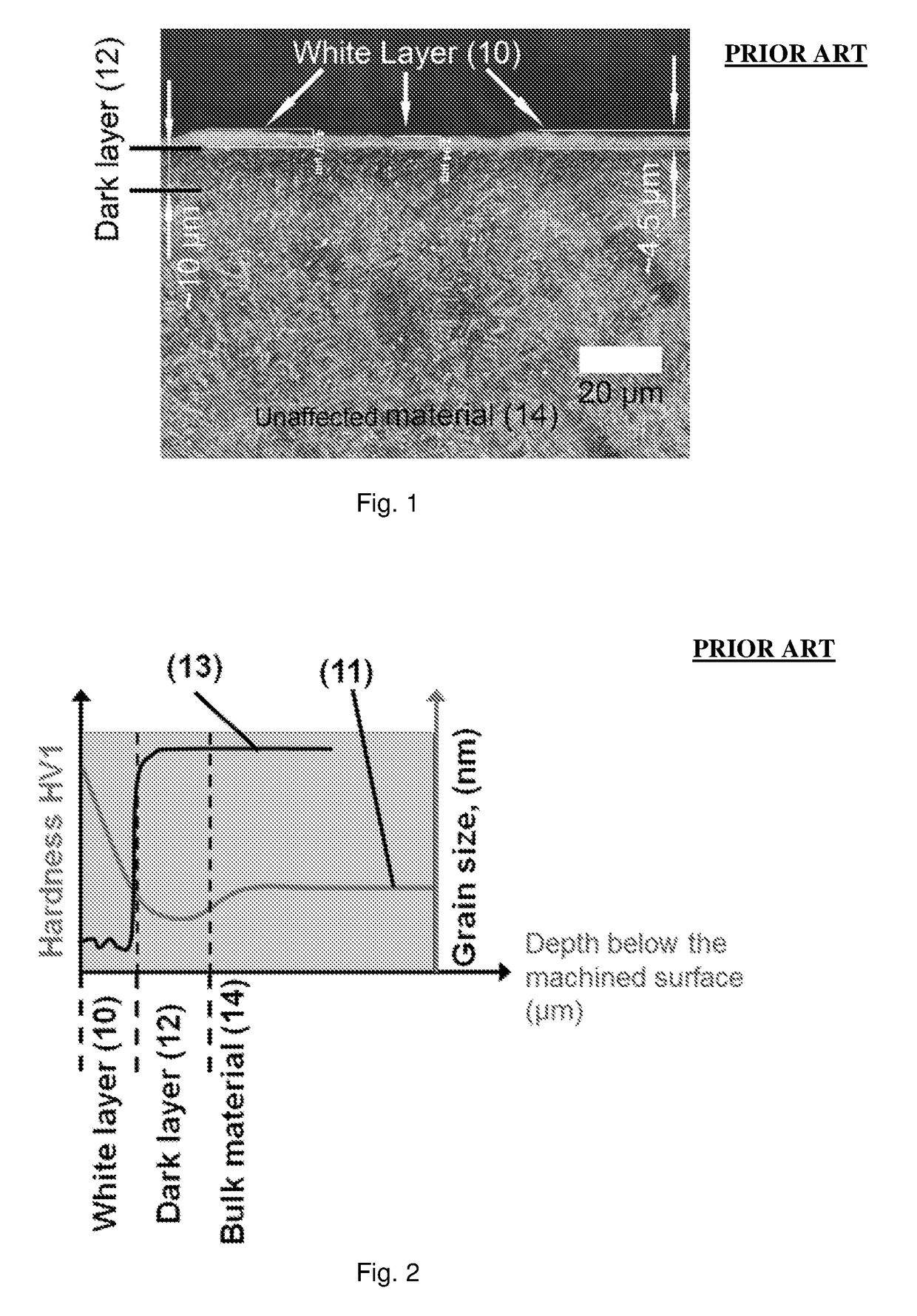
[0033]FIG. 1 shows a cross sectional view of a typical subsurface microstructure of an as-machined workpiece subjected to a hard machining process according to the prior art. The workpiece comprises a white layer 10, an underlying dark layer 12 directly adjacent to the white layer 10 and underlying unaffected material 14 directly adjacent to the dark layer 12.

[0034]The white layer 10 comprises evenly distributed carbides. The underlying dark layer 12, which is thicker than the white layer 12, also contains evenly distributed carbides. The unaffected material 14, which is unaffected by the hard machining process, comprises martensitic / bainitic needles having a length of about 2-3 μm and a width of about 0.5 μm. The martensitic / bainitic unaffected material also comprises evenly distributed carbides.

[0035]FIG. 2 shows the hardness profile 11 and the grain size 13 of an as-machined workpiece according to the prior art with depth below the as-machined surface, i.e. the uppermost surface ...


PUM

PropertyMeasurementUnit
Fractionaaaaaaaaaa
Lengthaaaaaaaaaa
Nanoscale particle sizeaaaaaaaaaa

Abstract

Bearing component providing unaffected material that has a surface, which has been subjected to a hard machining process during where the temperature of the surface did not exceed the austenitizing temperature of the unaffected material. The surface of the bearing component includes a white layer formed during the hard machining process. The white layer has a nano-crystalline microstructure that includes grains having a maximum grain size up to 500 nm. The white layer is located directly adjacent to the unaffected material of the bearing component, where no dark layer is formed during the hard machining process.

Description

FIELD OF THE INVENTION[0001]The present invention concerns a bearing component comprising unaffected material, such as steel, iron or an iron-based metal having a hardness of at least 45 HRC for example, which has been subjected to a machining process, such as hard machining, e.g. turning, or hard turning. The present invention also concerns a method for manufacturing such a bearing component.BACKGROUND OF THE INVENTION[0002]Hard turning is a machining process applied to metallic materials with a hardness greater than 45 HRC (which corresponds to about 450 HV1), and is typically performed after a workpiece has been heat treated. In hard turning a cutting tool describes a toolpath while a workpiece rotates. The tool's axes of movement may be a straight line, or they may be along some set of curves or angles. Usually the term “turning” is reserved for the generation of external surfaces by this cutting action, whereas this same essential cutting action when applied to internal surface...

Claims


Application Information

Patent Timeline
IPC IPC(8): F16C33/64F16C33/30
CPCF16C33/64F16C33/30F16C2202/04F16C2220/62F16C2240/06C22C38/18F16C19/00F16C33/14F16C33/32F16C33/34F16C2240/90
Inventor HOSSEINI, SEYEDKAMINSKI, JACEKSJOBLOM, ULF
Owner AB SKF
Learn More