
Low-dose x-ray imaging system

a low-dose x-ray and imaging system technology, applied in tomography, instruments, applications, etc., can solve the problems of inability to place extraordinarily the dentist, the detector configuration using the image intensifier and the collector is still too bulky to be used inside the mouth, and the sensor's quantum efficiency (qe) is reducing, so as to reduce the quantity of scattered x-rays

Active Publication Date: 2017-11-16
REAL TIME IMAGING TECH
View PDF8 Cites 0 Cited by
  • Summary
  • Abstract
  • Description
  • Claims
  • Application Information

AI Technical Summary

Benefits of technology

The present patent is related to a detector that can detect small amounts of light. The detector is designed to minimize interference from scattered X-rays and other non-photosensitive areas. The detector is enclosed within a light-proof housing which includes a radiation shielded back side. The detector also includes a focusing arrangement that uses a grid or microlens array to aim the light away from non-photosensitive areas and reduce the amount of scattered X-rays that hit the collector. The technical effects of this invention include improved accuracy and reduced noise in light detection, which can be useful in various applications such as medical imaging.

Problems solved by technology

The matrix and its wiring, however, reflect some of the light, and thus the photocathode layer can only receive the remainder of the incoming light; the reflection reduces the signal that is available to be captured resulting in a decrease in sensor's quantum efficiency (QE).
Despite these efforts, detector's configuration using the image intensifier and collector is still too bulky to be used inside the mouth and not ergonomic for the dentist to be placed extraorally while performing treatments on patients.
Another disadvantage of intensifiers is image distortion originating from the projection of the x-ray image onto the curved input phosphor, and a smaller component corresponding to the mapping from the input phosphor to the output phosphor and the digital image matrix.
Unfortunately, all of these approaches collect the light after going through the wiring layer and, as a result, the photocathode layer can only receive the remainder of the incoming light; the reflection reduces the signal that otherwise would be available for capture.

Method used


Image

  • Low-dose x-ray imaging system
  • Low-dose x-ray imaging system
  • Low-dose x-ray imaging system

Examples


Embodiment Construction

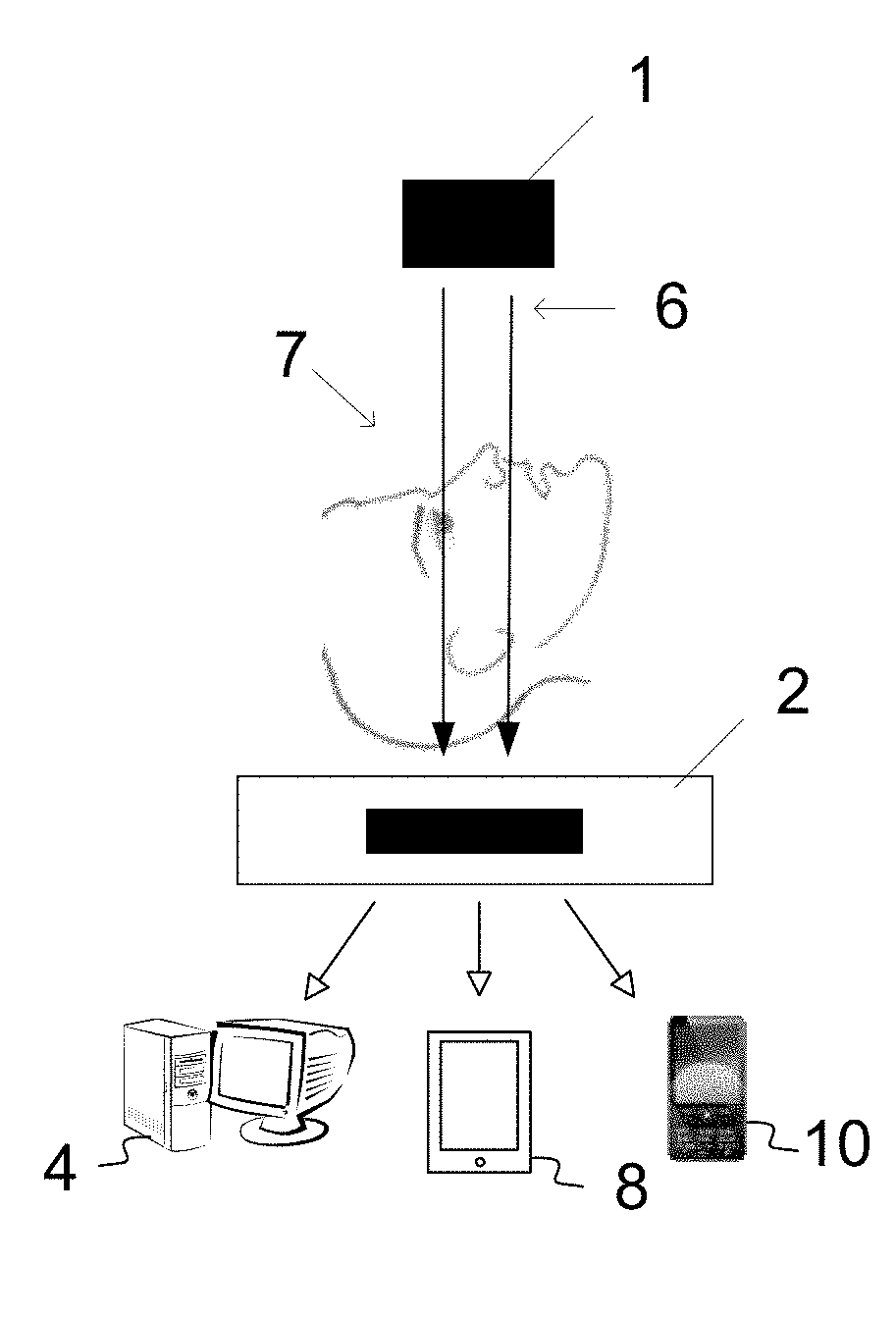
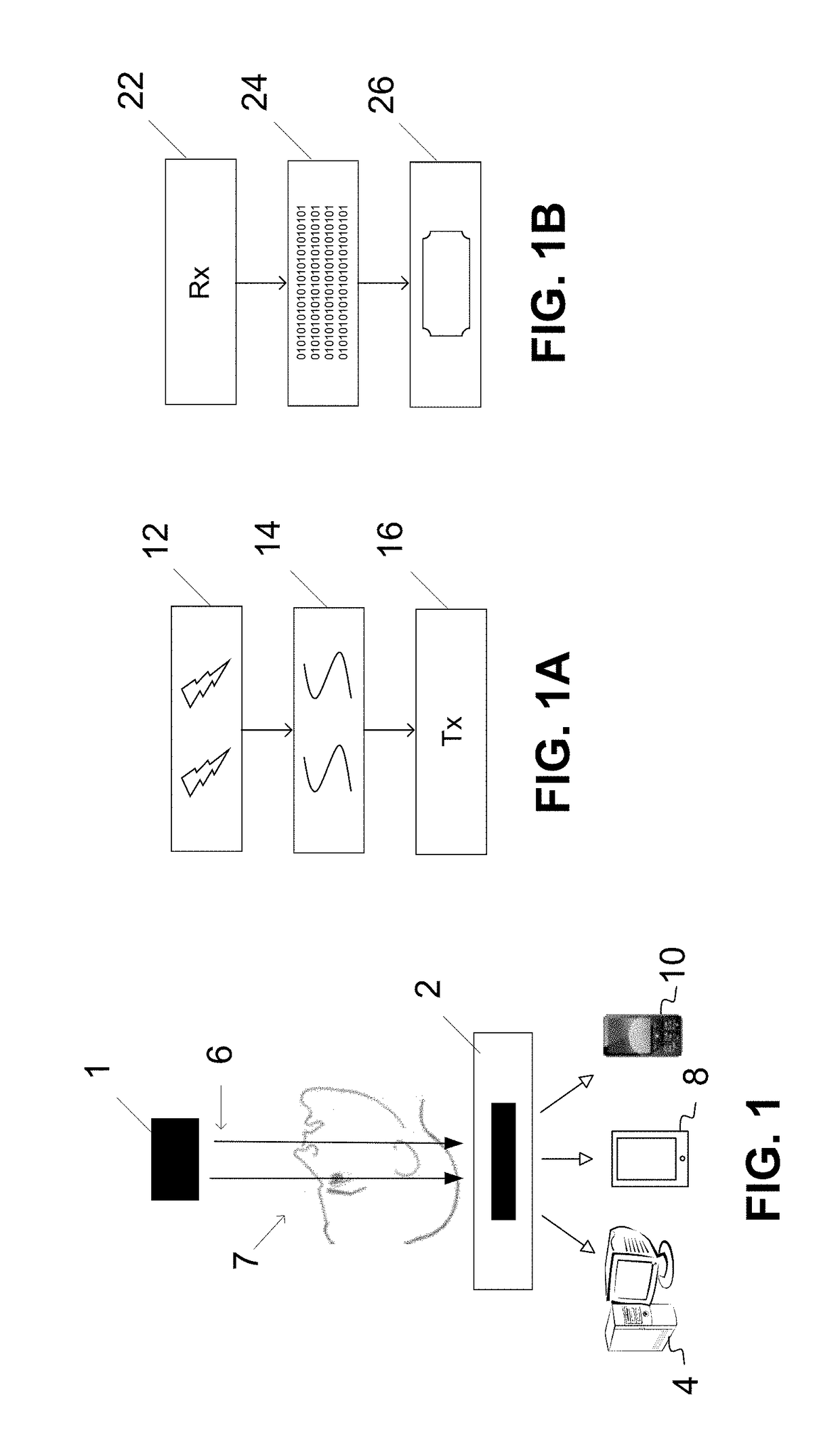
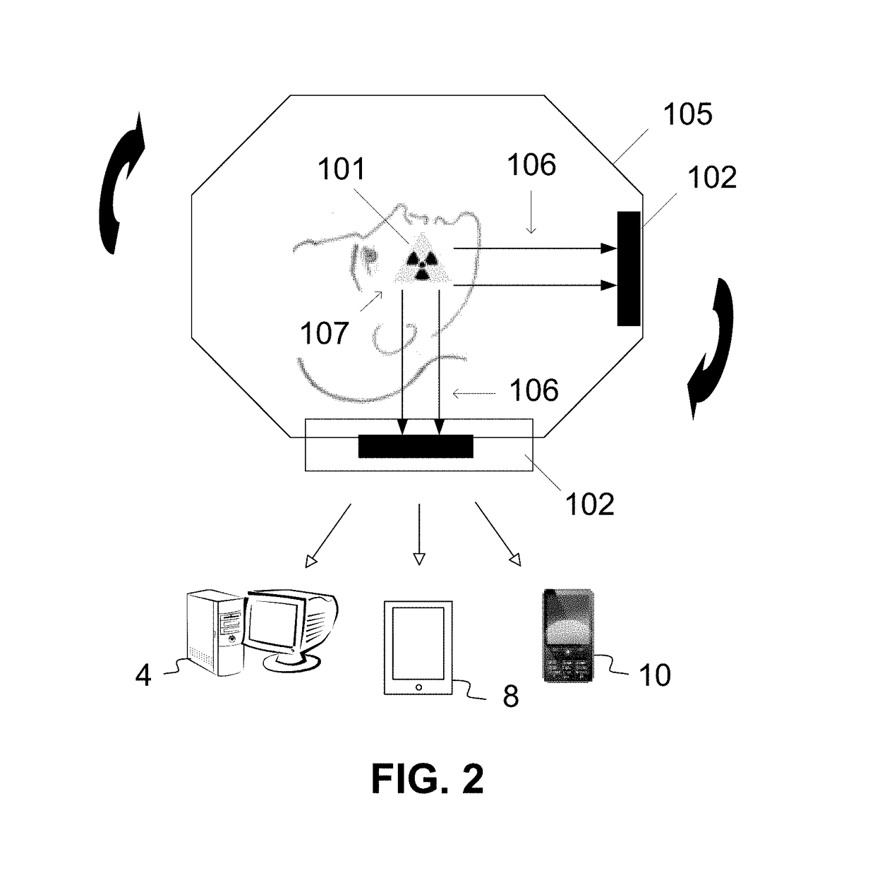
[0059]As a preliminary matter, it will readily be understood by one having ordinary skill in the relevant art (“Ordinary Artisan”) that the present invention has broad utility and application. As should be understood, any embodiment may incorporate only one or a plurality of the above-disclosed aspects of the invention and may further incorporate only one or a plurality of the above-disclosed features. Furthermore, any embodiment discussed and identified as being “preferred” is considered to be part of a best mode contemplated for carrying out the present invention. Other embodiments also may be discussed for additional illustrative purposes in providing a full and enabling disclosure of the present invention. As should be understood, any embodiment may incorporate only one or a plurality of the above-disclosed aspects of the invention and may further incorporate only one or a plurality of the above-disclosed features. Moreover, many embodiments, such as adaptations, variations, mod...


PUM


Abstract

A back illuminated sensor preferably is included as a collector component of a detector for use in intraoral and extraoral 2D and 3D dental radiography, positron emission tomography (PET) and single-photon emission computed tomography (SPECT). The disclosed imaging method includes one or more intraoral or extraoral emitters for emitting a low-dose gamma ray or x-ray beam through a dental examination area; and one or more intraoral or extraoral detectors for receiving the beam, each detector including a back illuminated sensor. Within the detector, the beam preferably is converted into light and then focused and collected at a photocathode layer without passing through the wiring layer of the back illuminated sensor.

Description

CROSS-REFERENCE TO RELATED APPLICATION[0001]For purposes of other than the United States, the present application claims the benefit of priority under the Paris Convention to U.S. nonprovisional patent application 62 / 102,216, filed Jan. 12, 2015, which application is incorporated by reference herein. For purposes of the United States, the present application is a U.S. nonprovisional patent application of, and claims priority under 35 U.S.C. §119 to, U.S. provisional patent application 62 / 102,216, filed Jan. 12, 2015, which application is incorporated by reference herein.COPYRIGHT STATEMENT[0002]All of the material in this patent document is subject to copyright protection under the copyright laws of the United States and other countries. The copyright owner has no objection to the facsimile reproduction by anyone of the patent document or the patent disclosure, as it appears in official governmental records but, otherwise, all other copyright rights whatsoever are reserved.BACKGROUN...

Claims


Application Information

Patent Timeline
IPC IPC(8): A61B6/00A61B6/03A61B6/14G01T1/24
CPCA61B6/5205A61B6/56G01T1/244A61B6/145A61B6/4405A61B6/037A61B6/512A61B6/51A61B6/5211
Inventor UZBELGER FELDMAN, DANIEL
Owner REAL TIME IMAGING TECH
Learn More